

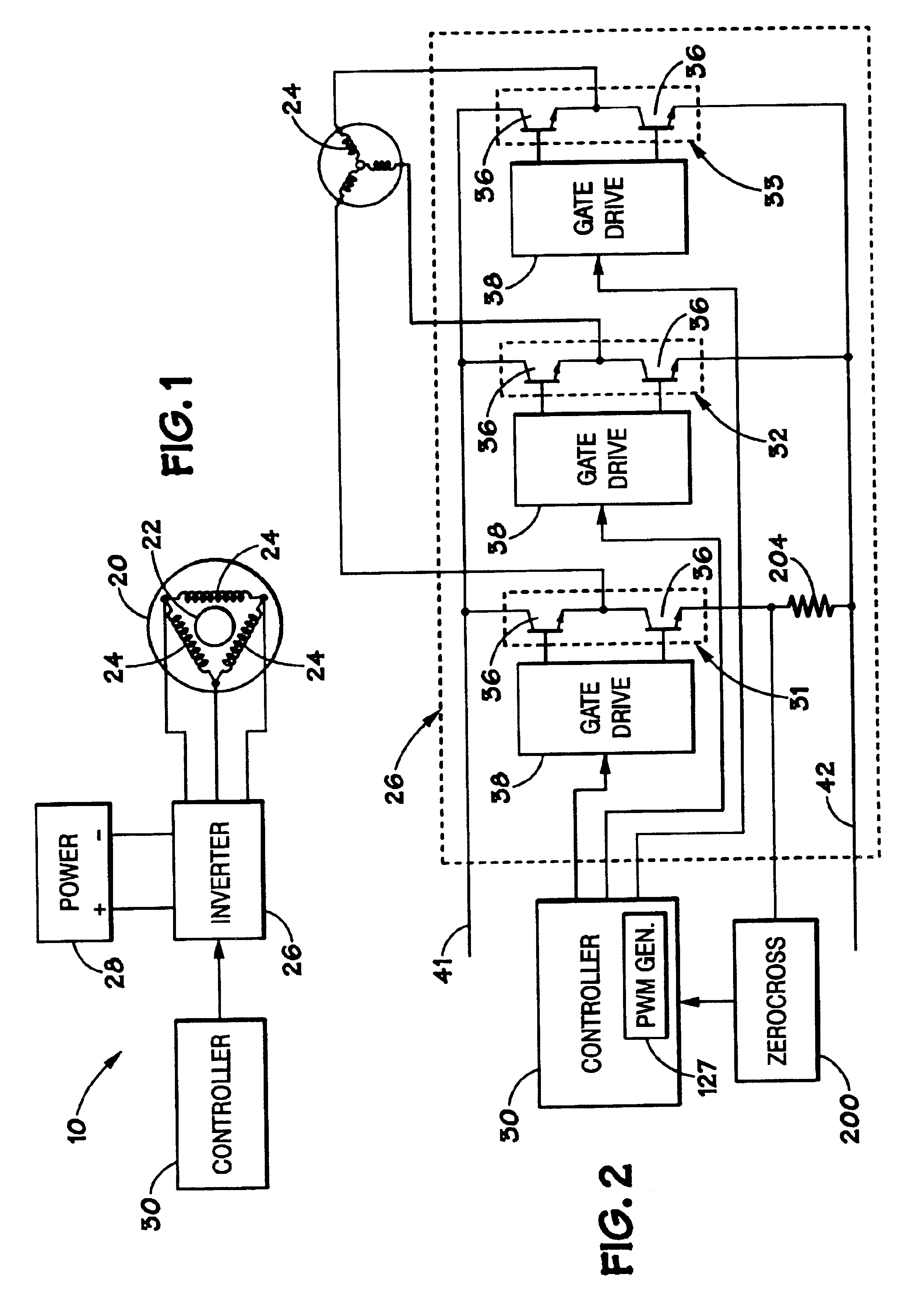
Induction motor control system
a technology of induction motor and control system, which is applied in the direction of power factor control, motor/generator/converter stopper, dynamo-electric converter control, etc., can solve the problem of not adequately addressing the requirements of a variable speed application
- Summary
- Abstract
- Description
- Claims
- Application Information
AI Technical Summary
Problems solved by technology
Method used
Image

Examples
Embodiment Construction
Illustrative embodiments of the invention are described below. In the interest of clarity, not all features of an actual implementation are described in this specification. It will of course be appreciated that in the development of any such actual embodiment, numerous implementation-specific decisions must be made to achieve the developers' specific goals, such as compliance with system-related and business-related constraints, which will vary from one implementation to another. Moreover, it will be appreciated that such a development effort might be complex and time-consuming, but would nevertheless be a routine undertaking for those of ordinary skill in the art having the benefit of this disclosure.
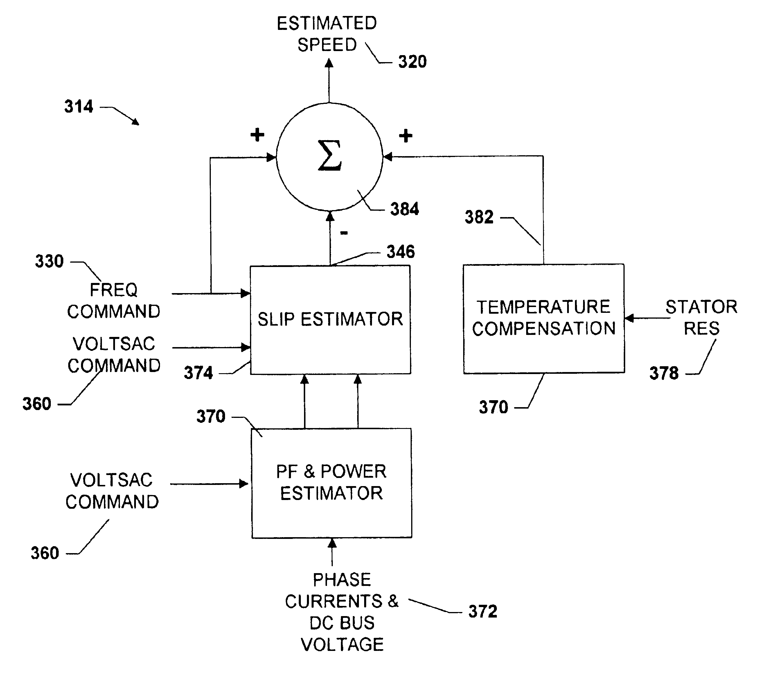
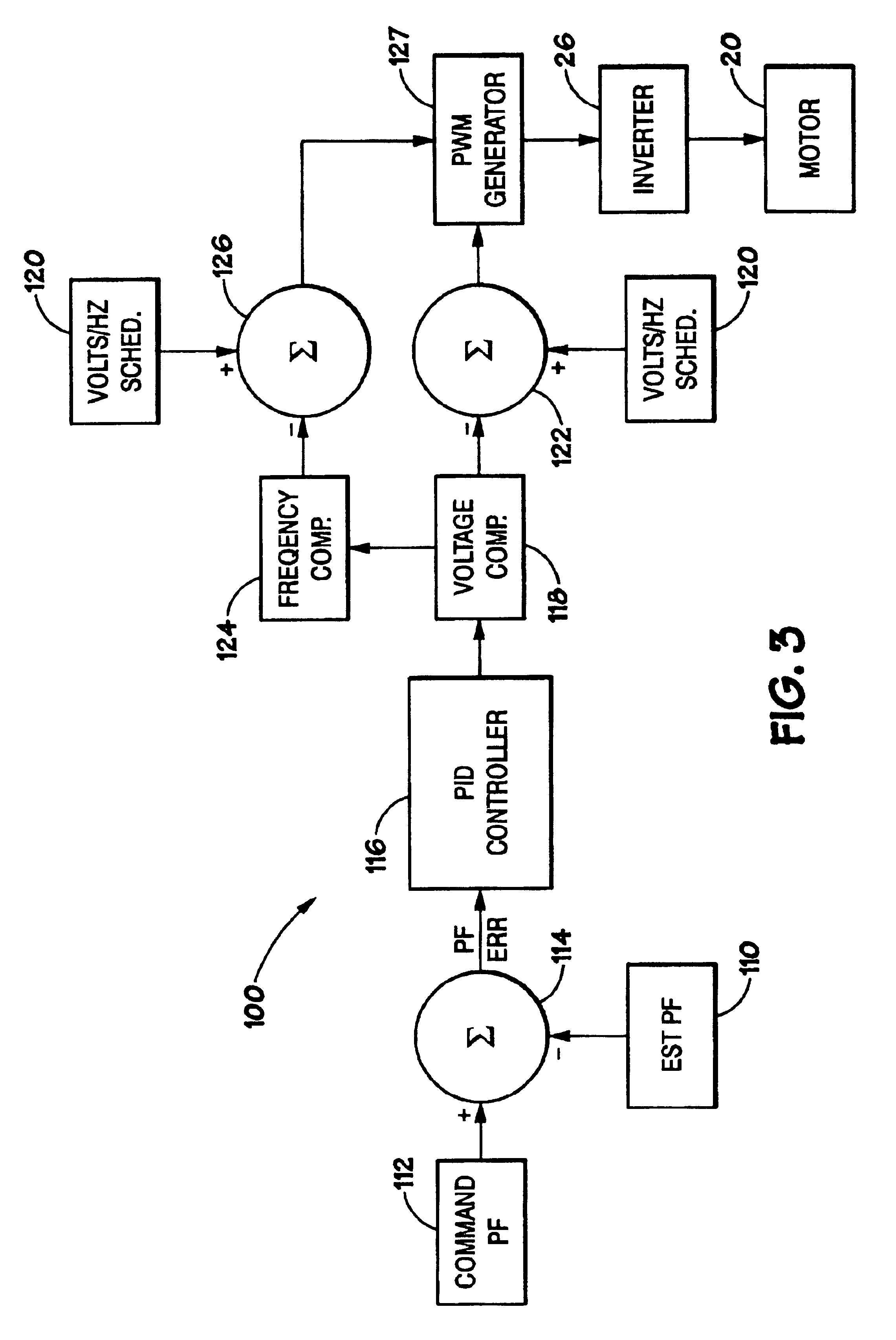
A constant slip speed in a motor ensures constant speed of the rotor at a constant input voltage frequency. Maintaining a constant slip also leads to a constant power factor operation under constant terminal voltage and frequency. This can be concluded from the equivalent circuit descr...
PUM
 Abstract
Description
Claims
Application Information