Non-contact power feeder

Inactive Publication Date: 2010-02-11
SAITAMA UNIVERSITY
View PDF1 Cites 72 Cited by
  • Summary
  • Abstract
  • Description
  • Claims
  • Application Information

AI Technical Summary

Benefits of technology

[0063]The non-contact power feeder according to the present invention has no load dependent characteristic, i.e., the capacitors Cs1 and Cp2 that form a resonance circuit do not depend on the load.
[0064]Additionally, in case of a resistive load, the power factor of the power supply output remains always 1, thereby providing high power factor and high conversion efficiency even if the load may vary. In case when the load has a reactance component, the power factor of the power supply output is always the same as the power factor of the load in the secondary side.
[0065]Moreover, since the secondary voltage and the secondary current are determined solely by the primary voltage, the

Problems solved by technology

However, since there is an air gap between the primary winding and the secondary winding unlike a clo

Method used


Image

  • Non-contact power feeder
  • Non-contact power feeder
  • Non-contact power feeder

Examples


first embodiment

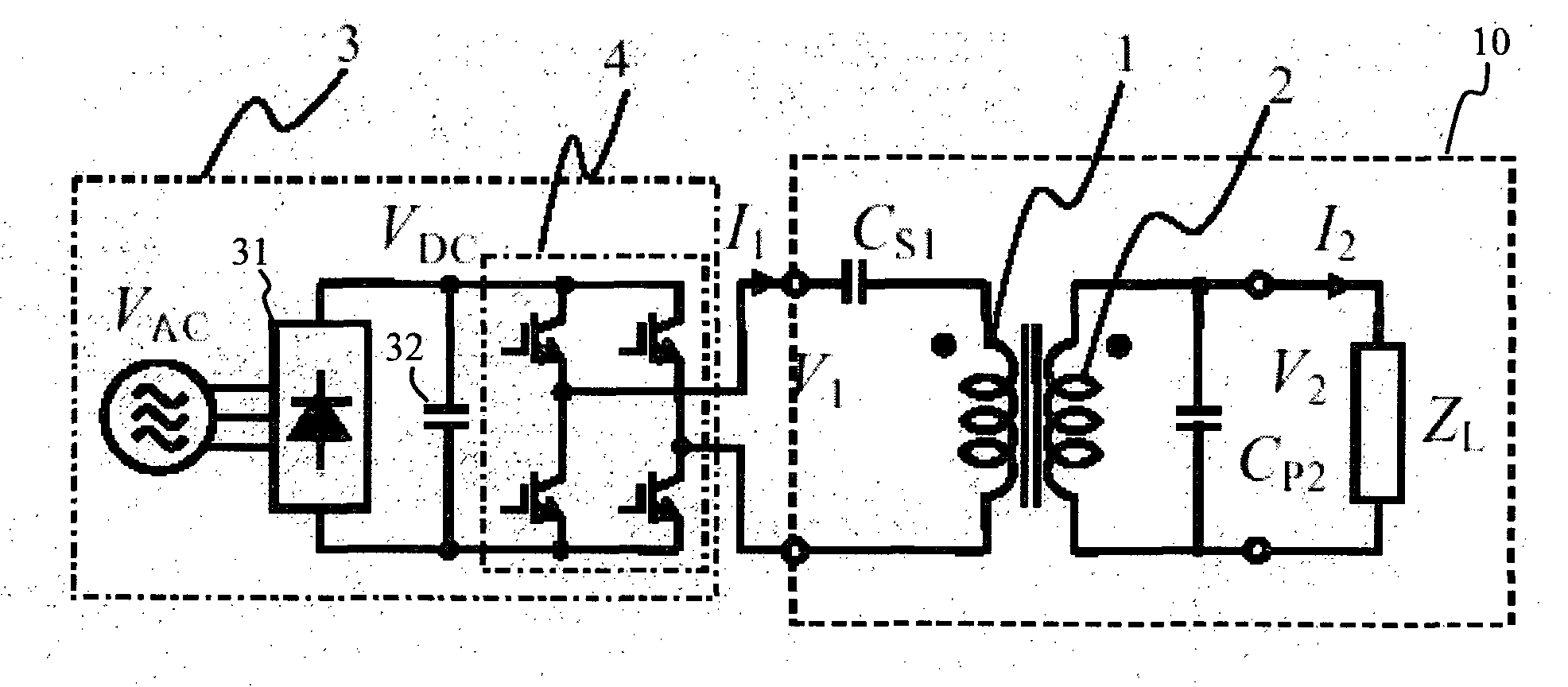
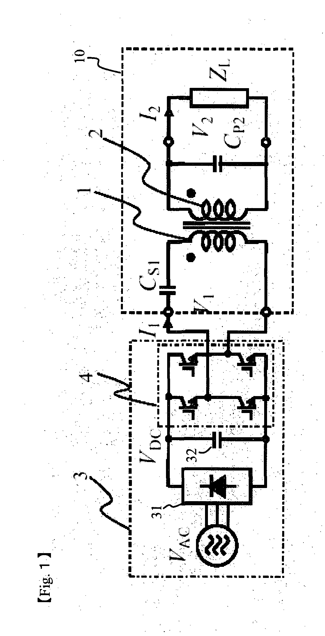
[0146]FIG. 1 illustrates a circuit configuration of the non-contact power feeder in a first embodiment of the present invention.

[0147]This power feeder comprises a high frequency AC power supply 3 and a non-contact power feeder portion 10 for supplying electric power outputted from the high frequency power supply 3 in a non-contact manner. The high frequency AC power supply 3 comprises a three-phase AC power supply VAC a rectifier 31 for rectifying the three-phase AC, a smoothing capacitor 32 and a voltage type inverter 4 for generating high frequency voltage using the rectified current and supplies AC in the range of several Hz to 100 kHz to the non-contact power feeder portion 10. Moreover, the non-contact power feeder portion 10 comprises a primary winding 1 and a secondary winding 2 of a transformer, a primary side capacitor Cs1 connected in series with the primary winding 1, a secondary side capacitor Cp2 connected in parallel with the secondary winding 2 and a load ZL to which...

second embodiment

[0173]In a second embodiment of the present invention, a description will be made on a non-contact power feeder in which the capacitors in the primary and secondary sides in the first embodiment are interchanged.

[0174]FIG. 7 shows a circuit configuration of this power feeder. The power feeder comprises a high frequency AC power supply 3 and a sine wave output inverter 9 as high frequency voltage generation means of the high frequency AC power supply 3. A non-contact power feeder section 10 comprises a primary side capacitor Cp1 connected in parallel with the primary winding 1 and a secondary side capacitor Cs2 connected in series with the secondary winding 2. The other configuration remains the same as the first embodiment (FIG. 1).

[0175]FIG. 8 is an equivalent circuit of the non-contact power feeder section 10 excluding the winding resistances r1, r2 and the iron loss r0. FIG. 9 illustrates (a) the basic configuration and (b) the equivalent circuit in this embodiment in a form conv...

third embodiment

[0192]Now, described is a third embodiment of the non-contact power feeder according to the present invention in which an inductor La is added to the secondary side in the first embodiment in order to vary the secondary voltage V2.

[0193]FIG. 11 illustrates the circuit configuration of this power feeder. An inductor La is added to the secondary side in this power feeder. Other configuration is the same as the first embodiment (FIG. 1).

[0194]Assuming that the reactance of the inductor La converted to the primary side is xa, it is given by the following (Expression 29):

xa=ω0×La  (Expression 29)

[0195]The equivalent circuit of the non-contact power feeder section 10 is the same as the equivalent circuits in FIG. 2-FIG. 4 except that the secondary leakage reactance x2 converted to the primary side is increased by xa, i.e., (x2+xa). Accordingly, the value of Cp2 is determined by the following (Expression 30) that is equal to the (Expression 16) for the first embodiment except replacing x2 ...


PUM


Abstract

[Problems] To provide a non-contact power feeder that is high efficient and high power factor and has no load dependence.
[Means for Solving Problems] A series capacitor Cs1 is connected to a primary winding 1 driven by an AC power supply 3 and a parallel capacitor Cp2 is connected to a secondary winding 2. The capacitance Cp is set to Cp≈1/{2πf0×(x0+x2)} and the capacitance Cs converted to the primary side is set to Cs≈(x0+x2)/{2πf0×(x0×x1+x1×x2+x2×x0)}, where f0 is the frequency of the power supply, x1 is a primary leakage reactance of the primary winding 1, x2 is a secondary leakage reactance of the secondary winding 2 converted to the primary side and x0 is an excitation reactance converted to the primary side. By setting Cp and Cs to the above values, the transformer of the non-contact power feeder is substantially equivalent to an ideal transformer. If it is driven by a voltage type converter, the output voltage (=load voltage) becomes substantially constant voltage regardless of the load. In case of a resistive load (ZL=R), the power factor of the power supply output always remains 1 even if the load may vary.

Description

TECHNICAL FIELD[0001]The present invention relates to a non-contact power feeder for feeding electric power to movable objects or electrical equipment in a non-contact manner.BACKGROUND[0002]Non-contact power feeding to movable objects such as transportation vehicles in a manufacturing plant, elevators and the like achieves to eliminate such problems as contact wear or sparks that are common to a trolley type power feeding or cable retention or entangling problems in cable power feeding, thereby simplifying maintenance. This is one of the reasons why non-contact power feeding devices are developed and put into practical use in recent years by applying the transformer principle, wherein an electrical power is supplied to a primary winding of a transformer and power is induced in a secondary winding by the electromagnetic induction for feeding power in a non-contact manner.[0003]FIG. 25 illustrates a device that is developed for non-contact power feeding to a movable object. This devi...

Claims


Application Information

Patent Timeline
IPC IPC(8): G05F3/04G05F1/12H02M7/48
CPCH02M3/3378H02J5/005H02J50/12H02J50/20
Inventor ABE, SHIGERUKANEKO, HIROYOSHI
Owner SAITAMA UNIVERSITY
Why Eureka
Try Eureka