Switching power device

a power device and power factor technology, applied in the direction of electric variable regulation, process and machine control, instruments, etc., can solve the problems of affecting the operation of the device, so as to reduce the size and weight of the device, suppress the generation of higher harmonics, and improve the power factor

Inactive Publication Date: 2006-03-30
YAMAHA CORP
View PDF3 Cites 72 Cited by
  • Summary
  • Abstract
  • Description
  • Claims
  • Application Information

AI Technical Summary

Benefits of technology

[0045] Moreover, the first capacitor is connected between the cathode of the first shunt regulator and the reference and the second capacitor is connected between the cathode of the second shunt regulator and the reference. Therefore, by setting the capacities of both of the capacitors to be several μF to several tens μF, for example, it is possible to feed back a fluctuation in the output current to be supplied to the load to the converter circuit at a much lower speed than the input AC frequency and to cause the input AC current to be proportional to the input AC voltage, thereby improving a power factor.
[0046] The switching power device according to the invention uses the non-capacitor flyback converter circuit in which a smoothing input capacitor having a large capacity is not provided. Therefore, the generation of a higher harmonic can be suppressed and a rush current preventing element is not required. Moreover, a high frequency power transformer taking a smaller size than the size of a lower frequency power transformer is used as a transformer. Consequently, it is possible to reduce the size and weight of the device. Furthermore, the negative feedback circuit feeds back a fluctuation in the output current to be supplied to the load to the converter circuit at a lower speed than the input AC frequency. By regulating the feedback speed of the negative feedback circuit, therefore, it is possible to cause the input AC current to be in-phase with the input AC voltage, thereby making the input AC current proportional to the input AC voltage. Consequently, it is possible to improve a power factor. Furthermore, the voltage control circuit controls the output voltage to be applied to the load so as to be a constant voltage and the output voltage is dropped in proportion to the output current to be supplied to the load when the output current exceeds the threshold. Therefore, it is possible to use a capacitor having a low breakdown voltage to some degree which smoothes a switching voltage induced to a secondary winding, and furthermore, to have the same output characteristic as that in the power device comprising the low frequency power transformer.

Problems solved by technology

However, there are the following problems in the design of the conventional audio amplifier.
More specifically, in the case in which a power device comprising a low frequency power transformer is used, there is a problem in that many restrictions are imposed in respect of a design when a low frequency power transformer is used as a small-sized integral type power supply for a multichannel audio amplifier because the volume of each low frequency power transformer is large.
When a low frequency power transformer having a small size is used in order to eliminate the restrictions in respect of the design, moreover, a load regulation is deteriorated.
In addition, when the copper loss of the low frequency power transformer is decreased to enhance the load regulation, there is a problem in that a power factor and a power harmonic are deteriorated.
There is a problem in that this property is hard to control optionally.
On the other hand, in the case in which a switching power device is to be used, a high frequency power transformer has a small copper loss.
Consequently, the output of an amplifier becomes excessive.
Therefore, tough conditions are set.
If the total output of the audio amplifier in the full-channel simultaneous output has the value obtained by adding outputs in the driving operation of only one channel corresponding to all of the channels as described above, however, there is no advantage to a user and the temperature test becomes uselessly strict.

Method used


Image

  • Switching power device
  • Switching power device
  • Switching power device

Examples


Embodiment Construction

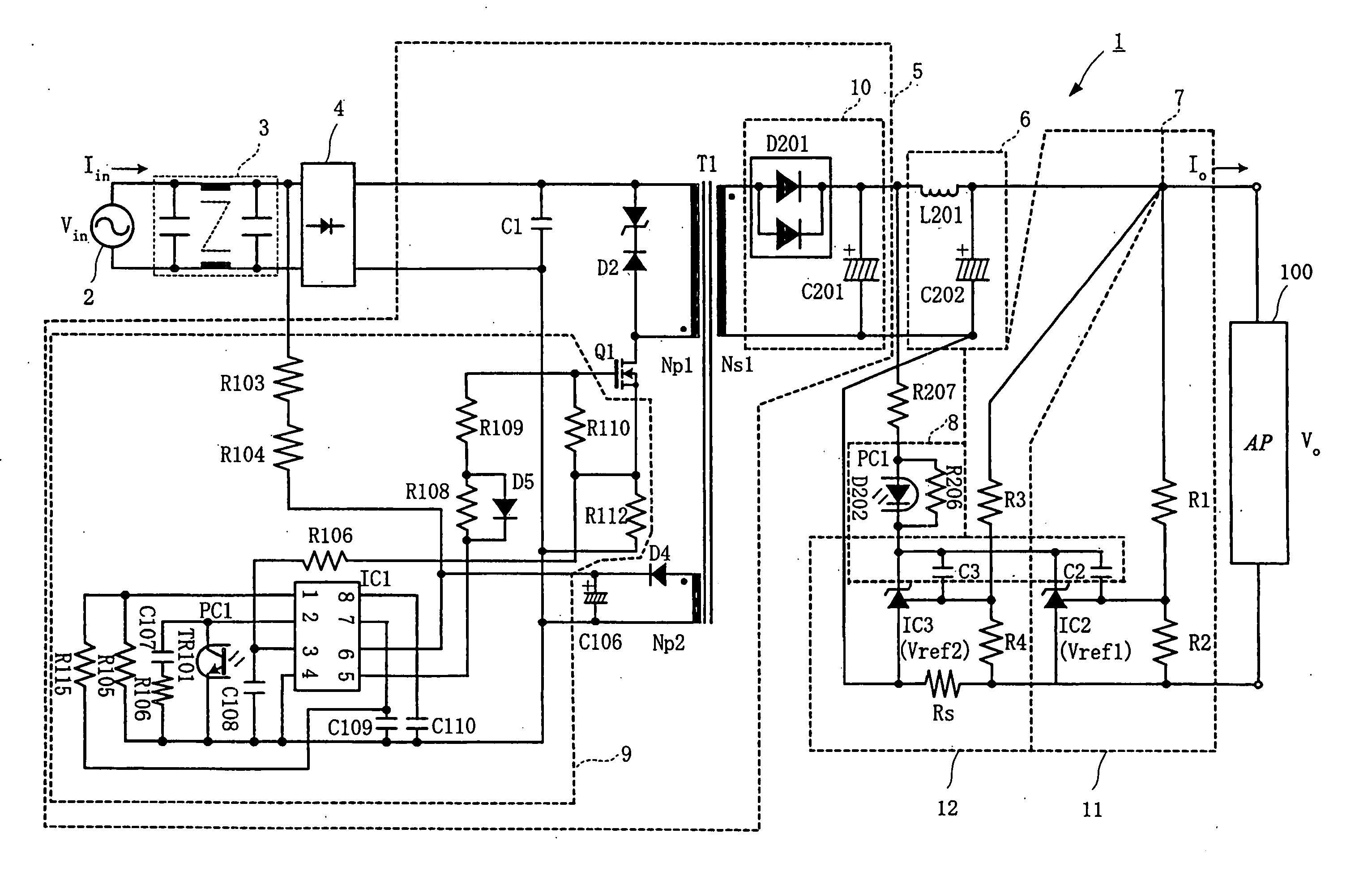
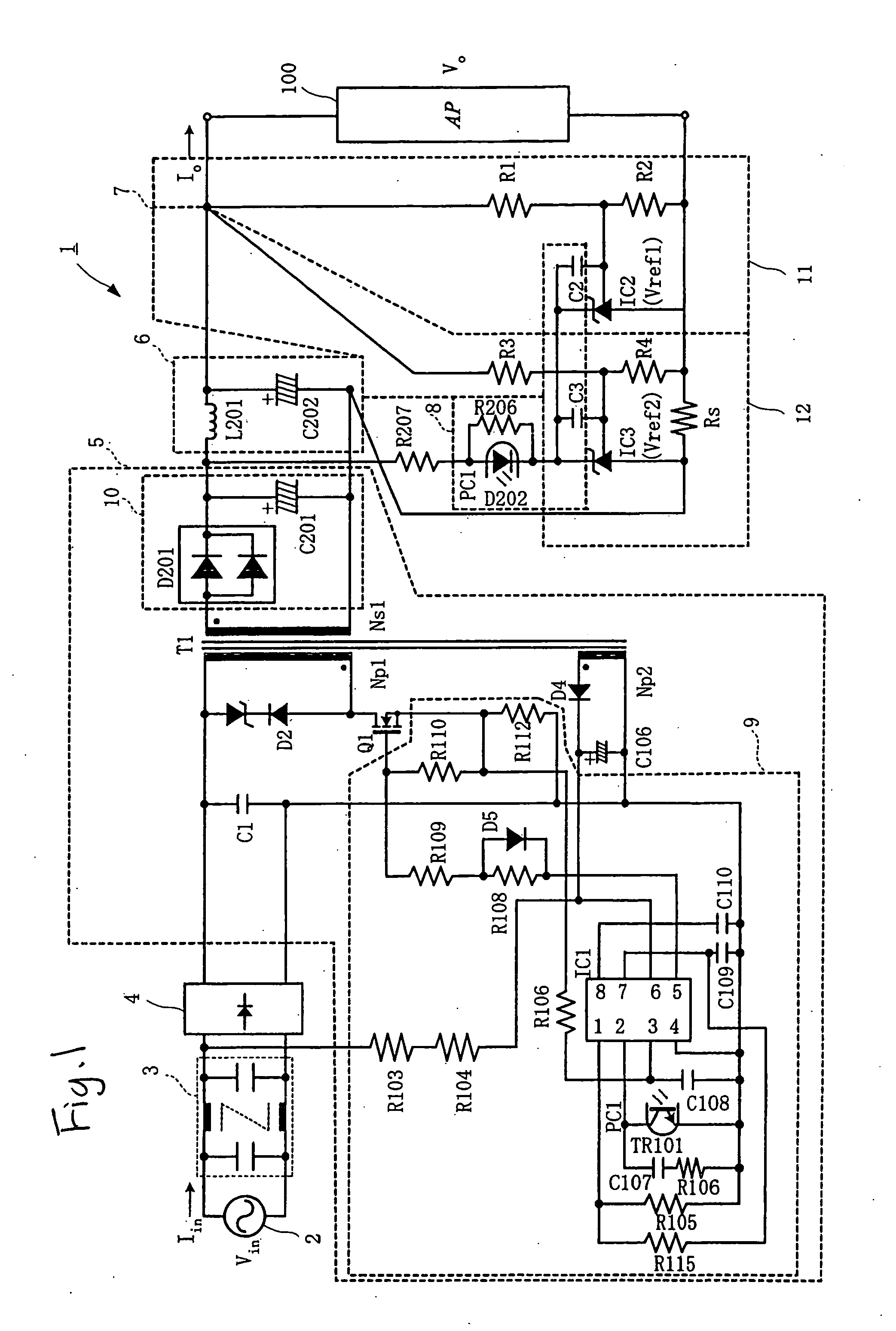
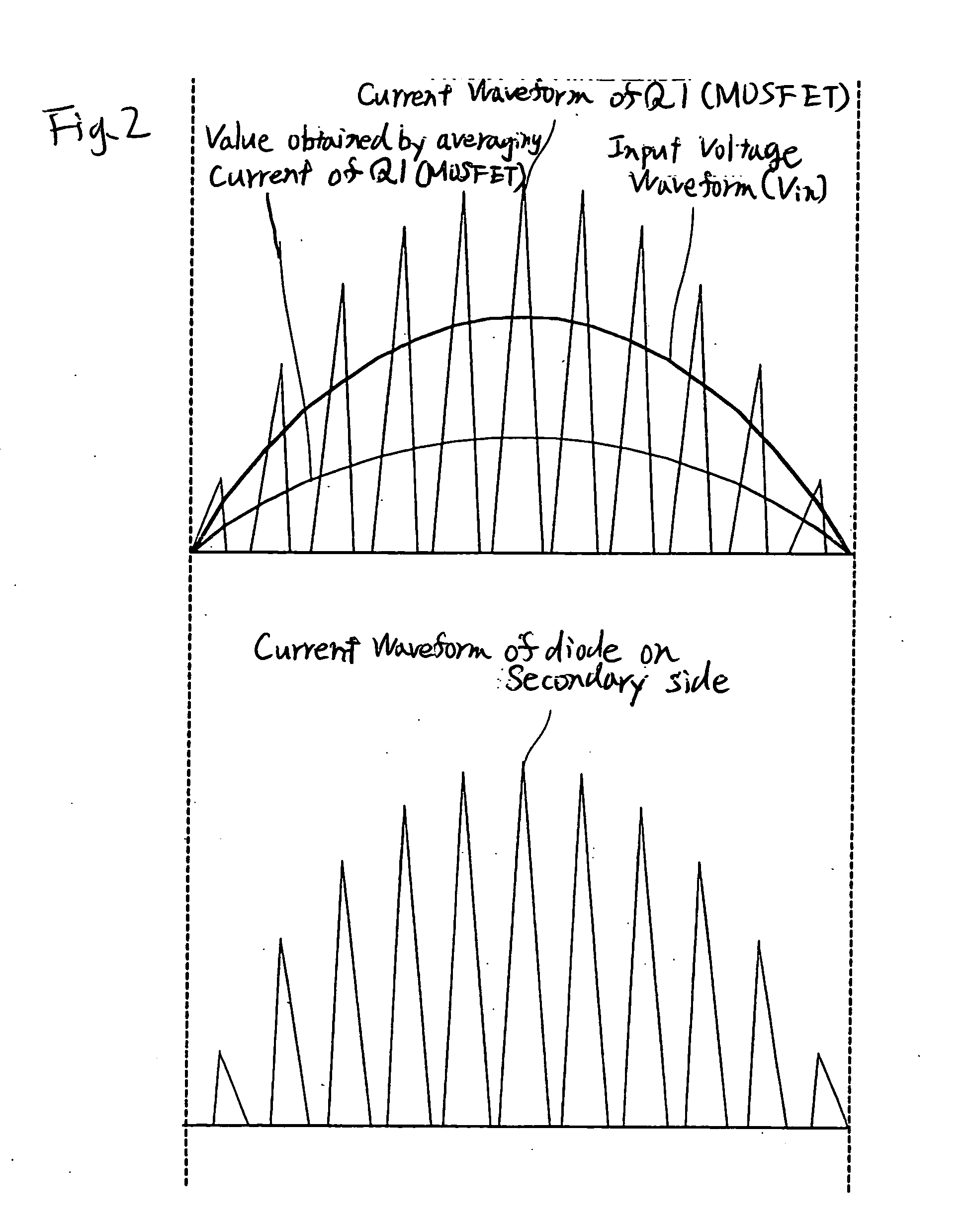
[0056] An embodiment of a switching power device according to the invention will be described below in detail. FIG. 1 is a circuit diagram showing the structure of the switching power device according to the embodiment of the invention. FIG. 2 is a waveform diagram showing an input voltage, an input current and an output current in the flyback transformer of the switching power device. In the following description, a switching power device 1 according to the invention is applied to a power circuit for an audio amplifier. For the audio amplifier, it is suitable to use an analog amplifier having a high SVRR and a digital audio amplifier of a feedback type.

[0057] The switching power device 1 is connected to a commercial AC power supply 2 and comprises a noise filter 3, a rectifier circuit 4, an input non-capacitor flyback converter (hereinafter referred to as a non-capacitor converter) 5, a noise filter 6, a voltage control circuit 7 and a negative feedback circuit 8.

[0058] The noise...


PUM


Abstract

A switching power device uses a non-capacitor flyback converter circuit not provided with a smoothing input capacitor having a large capacity. Therefore, a power harmonic can be suppressed and a rush current preventing element is not required. A fluctuation in an output current to be supplied to a load is fed back to the non-capacitor flyback converter circuit by a feedback circuit at a lower speed than an input AC frequency. Therefore, it is possible to improve a power factor by causing an input AC current to be proportional to an input AC voltage. A voltage control circuit controls an output voltage so as to have a constant voltage, and the output voltage is dropped in proportion to an output current when the output current exceeds a threshold. Therefore, it is possible to have the same output characteristic as a power device comprising a low frequency power transformer.

Description

BACKGROUND OF THE INVENTION [0001] The present invention relates to a switching power device for an audio amplifier which comprises a low frequency power transformer, eliminates the respective drawbacks of a power supply and a switching power supply and has both advantages. [0002] As a power device for an audio amplifier, conventionally, there have been used a power device utilizing a low frequency power transformer and a switching power device (for example, see Patent Documents 1 and 2). [0003] Patent Document 1: JP-A-7-274388 Publication [0004] Patent Document 2: JP-A-5-176532 Publication [0005] When designing a power supply for an audio amplifier, it is necessary to take care of the following respects. [0006] 1. The audio amplifier is to reproduce a voice at a lower limit (20 Hz) of a voice frequency or less. For this reason, it is necessary to provide a capacitor having a large capacity in the output of the power supply for the audio amplifier. [0007] 2. It is desirable that the...

Claims


Application Information

Patent Timeline
Patent Type & Authority Applications(United States)
IPC IPC(8): H05B41/36
CPCH05B41/282
Inventor ISHIGAKI, YUZONORO, MASAO
Owner YAMAHA CORP
Why Eureka
Try Eureka