Three phase buck power converters having input current control

a power converter and input current technology, applied in the field of power converters, can solve the problems of large inrush current, notoriously slow response of three phase power converters with power factor correction

Inactive Publication Date: 2006-11-21
HERBERT EDWARD
View PDF7 Cites 76 Cited by
  • Summary
  • Abstract
  • Description
  • Claims
  • Application Information

AI Technical Summary

Benefits of technology

[0006]With respect to the usual three phase commercial ac power source, it can be considered to be a near ideal voltage source, in that the voltage waveform will not be greatly affected by the load (the power converter input). For these applications, the input voltage is sufficiently solid that it can be used as the voltage and waveform reference, the only concern being variations in the voltage magnitude, which can be compensated.
[0007]In the case of a three phase input from a free-wheeling power source, such as a wind or water turbine, an overrunning load or dynamic braking, the voltage, frequency and waveform are not stable, so a master waveform generator must provide a reference having he desired frequency and waveform. The magnitude component is varied, probably by a means for feedback control as the control variable. The frequency and waveform of the model as well as the magnitude can be varied arbitrarily fast so long as they don't exceed the rate at which the free-wheeling power source can follow. The present invention teaches a method of very solid current control, and to a large extent this current control can maintain the desired three phase ac currents whether the voltage is leading or lagging and regardless of its magnitude.

Problems solved by technology

Upon application of the input power, large inrush currents occur.
Present three phase power converters with power factor correction are notoriously sluggish in their response to transients.

Method used


Image

  • Three phase buck power converters having input current control
  • Three phase buck power converters having input current control
  • Three phase buck power converters having input current control

Examples


Embodiment Construction

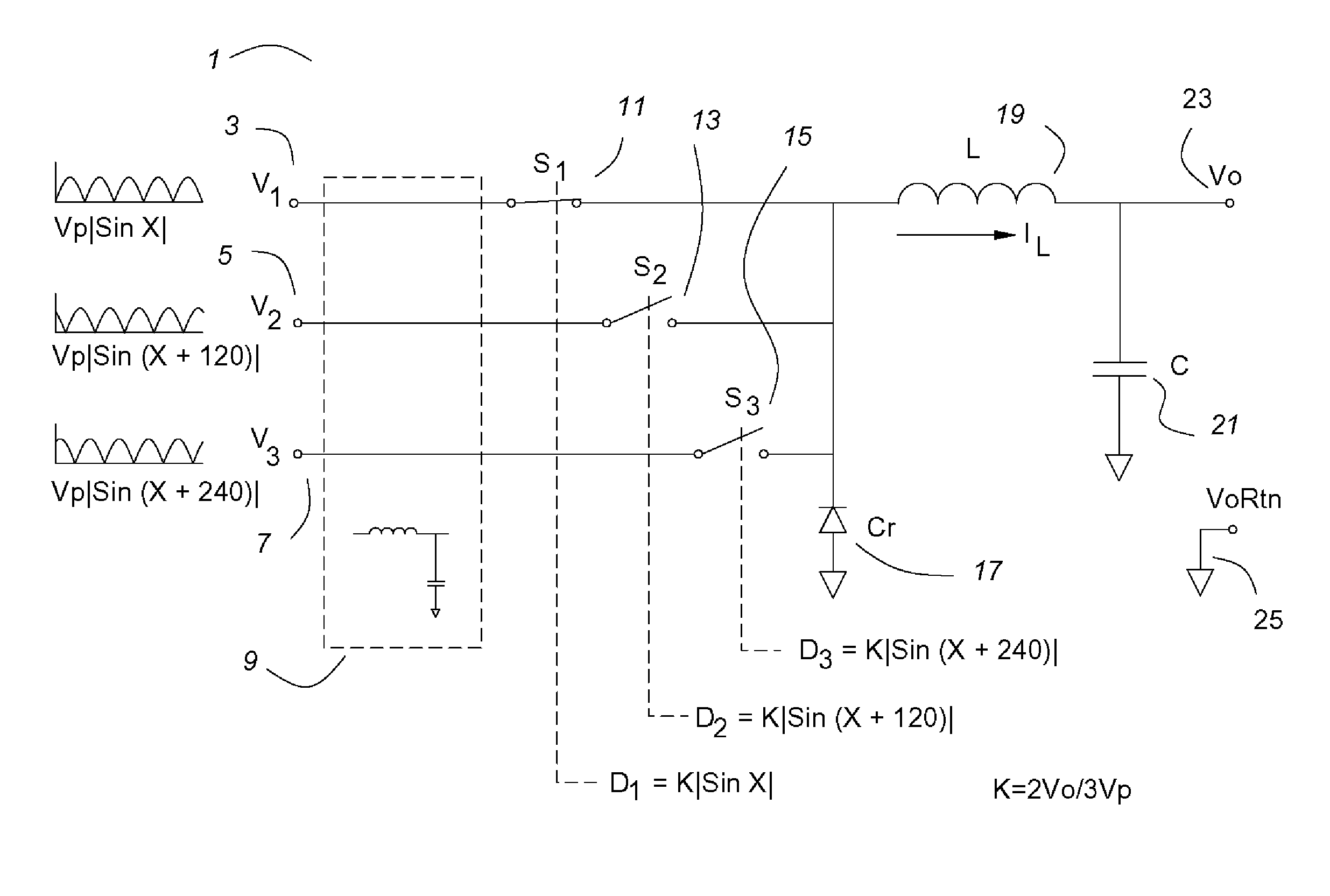
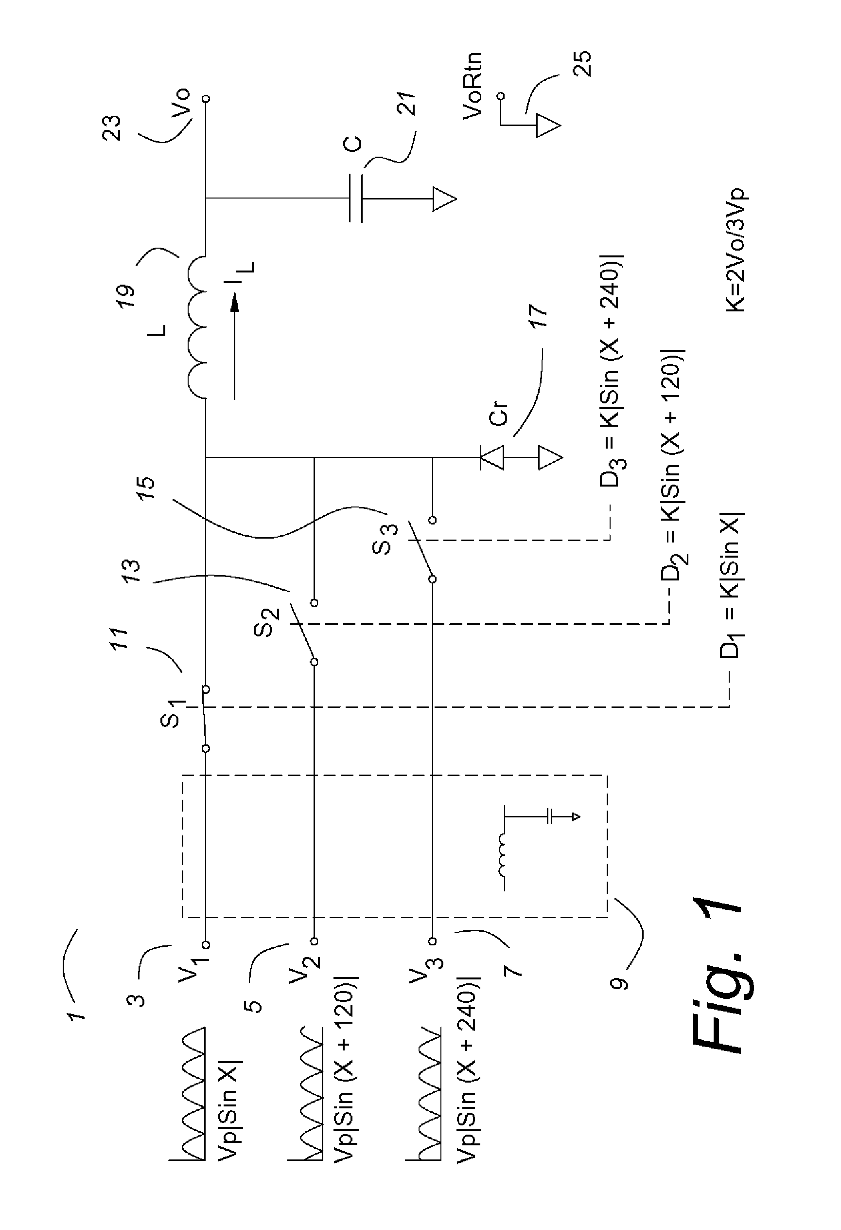
[0069]FIG. 1 shows the basic parts of a three phase buck converter 1 having power factor correction. The three input voltages V13, V25 and V3 are full wave rectified three phase sine waves having a peak magnitude Vp. An input filter 9 is shown with no detail. As with any buck inverter, the input must be filtered to prevent the high frequency current pulses from propagating, for emi (electromagnetic interference) reasons as well as to present a very low impedance to the buck converter at the pwm (pulse width modulation) frequency. The design and application of input filters is well know to one skilled in the art of power converters and could be designed and applied without undue experimentation, but would vary widely depending upon the requirements of a particular application. In this specification and the claims, any recitation of a three phase ac voltage source (or load, in the case of the boost variant) includes filtering as necessary and appropriate for a particular application. ...


PUM


Abstract

A three phase buck power converter having input power control is described. The power converter uses a three input buck converter comprising switches for each phase, a catch rectifier, an inductor and an output capacitor. The duty cycle of the three switches is constrained to have a sine function relationship that may be derived from the input voltage wave form or from a reference oscillator. When so constrained, the input currents have high power factor. The output is a precise, high quality dc voltage, comparable to the output of a dc—dc buck converter, and the dynamic response is comparable. Voltage mode and current mode controls are shown, as is a precise line regulation feed forward for the voltage mode embodiment. The three phase buck power converter may be operated in reverse as a three phase boost converter, as they are reciprocal. A three phase ac—ac converter may have a three phase buck converter as its input and a three phase boost converter as its output.

Description

CROSS REFERENCE TO RELATED APPLICATIONS[0001]This application claims priority to the filing date of a provisional application entitled “Three Phase Buck Power Converters Having Power Factor Correction”, Ser. No. 60 / 522,330, filed Sep. 15, 2004.BACKGROUND OF THE INVENTION[0002]This invention relates to power converters, and more particularly to power converters having a three phase ac input and requiring power factor correction. This invention also relates to control of the input current and frequency of free-wheeling power sources, dc to three phase ac conversion and three phase ac to three phase ac power conversion, particularly when the frequencies differ.[0003]Usually power factor correction is accomplished by monitoring the three input currents using three input current shunts or current transformers or the like. A sine wave current reference is also generated for each phase, often using the ac voltage inputs. The measured currents are compared to the current references and a fe...

Claims


Application Information

Patent Timeline
Patent Type & Authority Patents(United States)
IPC IPC(8): H02M7/00
CPCH02M1/42H02M7/2176H02M2001/4291Y02B70/12Y02B70/126H02M1/4291Y02B70/10Y02P80/10
Inventor HERBERT, EDWARD
Owner HERBERT EDWARD
Why Eureka
Try Eureka