Time-based current control in switching regulators

a switching regulator and current control technology, applied in the direction of dc-dc conversion, power conversion systems, instruments, etc., can solve the problems of large ripple voltage at large ripple current on the output of the regulator, and large ripple current. , to achieve the effect of low ripple and efficient voltage regulation

Inactive Publication Date: 2006-01-17
ANALOG DEVICES INT UNLTD
View PDF8 Cites 35 Cited by
  • Summary
  • Abstract
  • Description
  • Claims
  • Application Information

AI Technical Summary

Benefits of technology

[0009]It is therefore a object of the present invention to provide voltage regulators that have the benefits of current mode cont

Problems solved by technology

The abrupt switching and accompanying discharge of energy stored in inductive filter elements typically results in undesirably large ripple voltages at the output of the regulator.
In many instances, the peak inductor current rises to relatively large levels due to the size of the inductor required to accommodate worst-case operating scenarios of the regulator.
As a result, a significant amount of ripple may be present on the regulator output.
The method of using a single peak current threshold for current mode control, however, may not be satisfac

Method used


Image

  • Time-based current control in switching regulators
  • Time-based current control in switching regulators
  • Time-based current control in switching regulators

Examples


Embodiment Construction

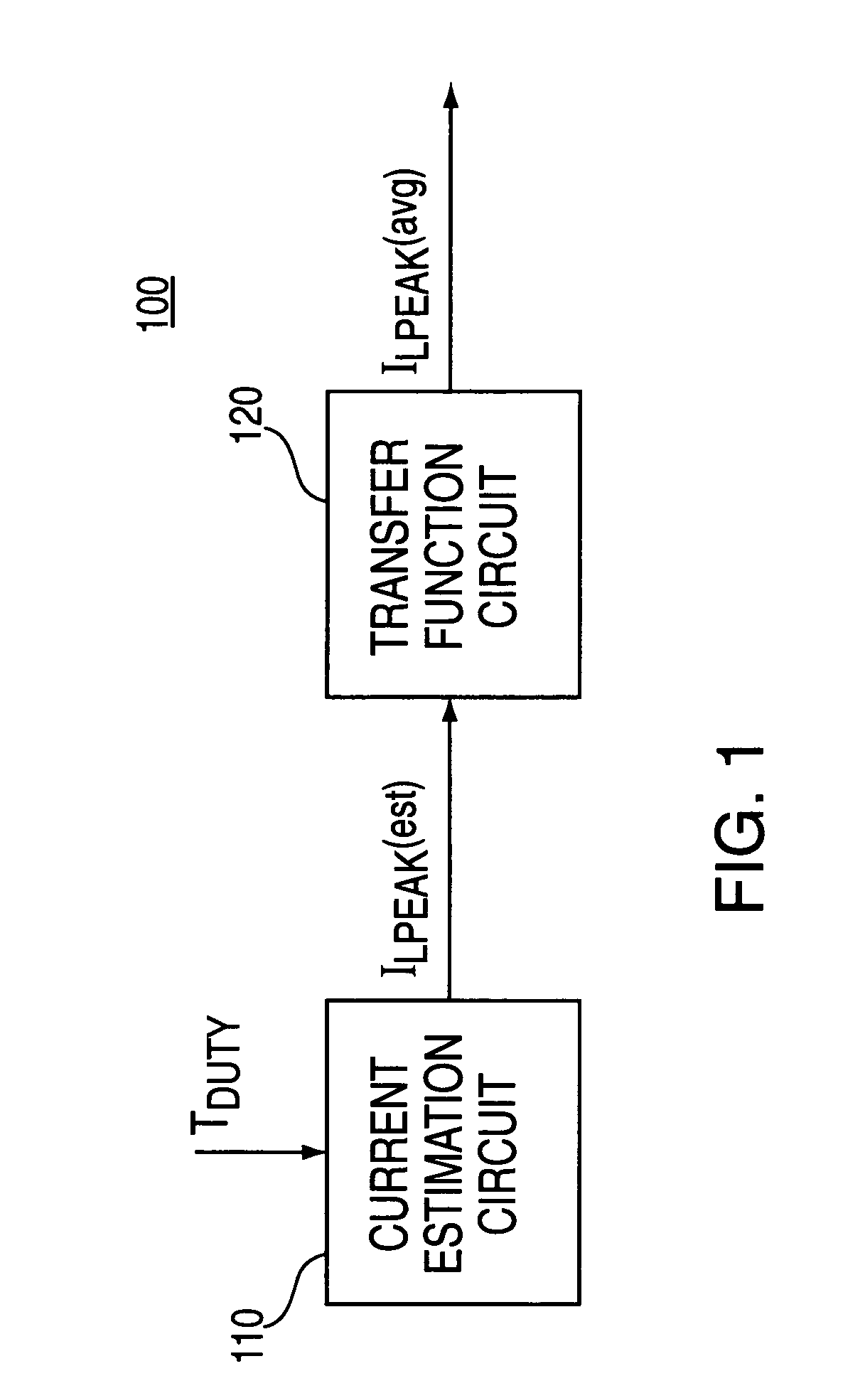
[0022]FIG. 1 is an illustrative block diagram of a time-based current control system 100 constructed in accordance with the principles of the present invention that can be used to regulate the output of a switching regulator. System 100 may include two sections: a current estimation circuit 110 and a transfer function circuit 120.

[0023]During operation, a signal (TDUTY) indicative of the duty cycle of a switching regulator (not shown) is provided to current estimation circuit 110. TDUTY may be, for example, a control signal used to command a switching element in the regulator ON and OFF (or a signal derived therefrom). Estimation circuit 110 generates an output signal ILPEAK(est) in response to TDUTY that is an estimation of the switching regulator's peak output current. This estimation may be performed in various ways. One way is to measure the period of TDUTY and make an approximation of output current based on the amount of time the switching element is held ON or OFF. Once this ...


PUM


Abstract

Control circuits that employ time-based current control methods for switching voltage regulators are provided. The control circuit includes a current estimation circuit and optionally, a transfer function circuit. The current estimation circuit generates estimates of regulator output current as function of switch period for use as a threshold indicative of peak current limit. This arrangement eliminates the need for error amplifiers to provide effective current mode control. The absence of error amplifiers allows fabrication of switching regulators on smaller die areas and provides switching regulators with reduced power consumption.

Description

BACKGROUND OF THE INVENTION[0001]The present invention relates to switching regulator circuits. More particularly, the present invention relates to circuits and methods for regulating output voltage based on approximations of load current.[0002]The purpose of a voltage regulator is to provide a predetermined and substantially constant output voltage to a load from a poorly-specified and fluctuating voltage source. One type of voltage regulator commonly used to accomplish this task is a switching voltage regulator. Switching voltage regulators are typically arranged to have a switching element, such as a power transistor, coupled between the voltage source and the load. The switching regulator controls the voltage across the load by turning the switching element ON and OFF so current passes through it and into an inductor in the form of discrete current pulses. The inductor and an output capacitor then convert these current pulses into a substantially steady load current so that the ...

Claims


Application Information

Patent Timeline
IPC IPC(8): G05F1/445
CPCH02M3/156H02M2001/0009H02M1/0009
Inventor LEE, DAMON
Owner ANALOG DEVICES INT UNLTD
Why Eureka
Try Eureka