
Switching converter for power domain separation

a technology of switching converter and power domain, applied in the direction of power conversion system, dc-dc conversion, instruments, etc., to achieve the effect of minimal output filtering and low rippl

Active Publication Date: 2021-01-21
ANALOG DEVICES INT UNLTD
View PDF0 Cites 1 Cited by
  • Summary
  • Abstract
  • Description
  • Claims
  • Application Information

AI Technical Summary

Benefits of technology

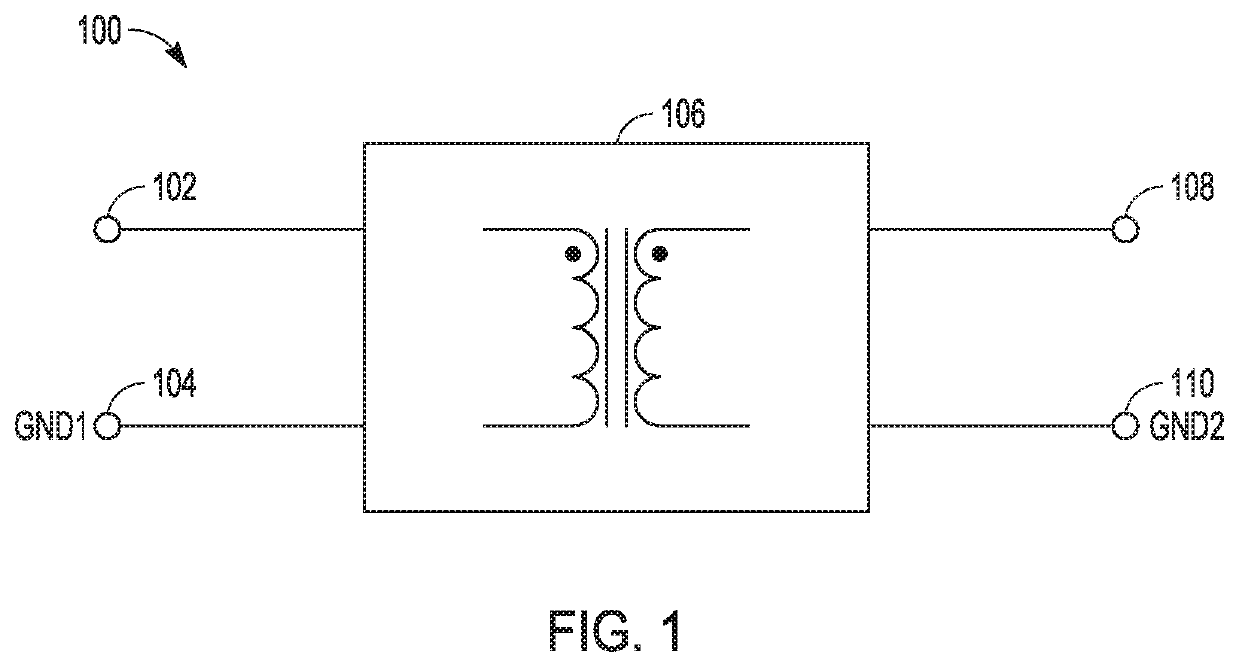
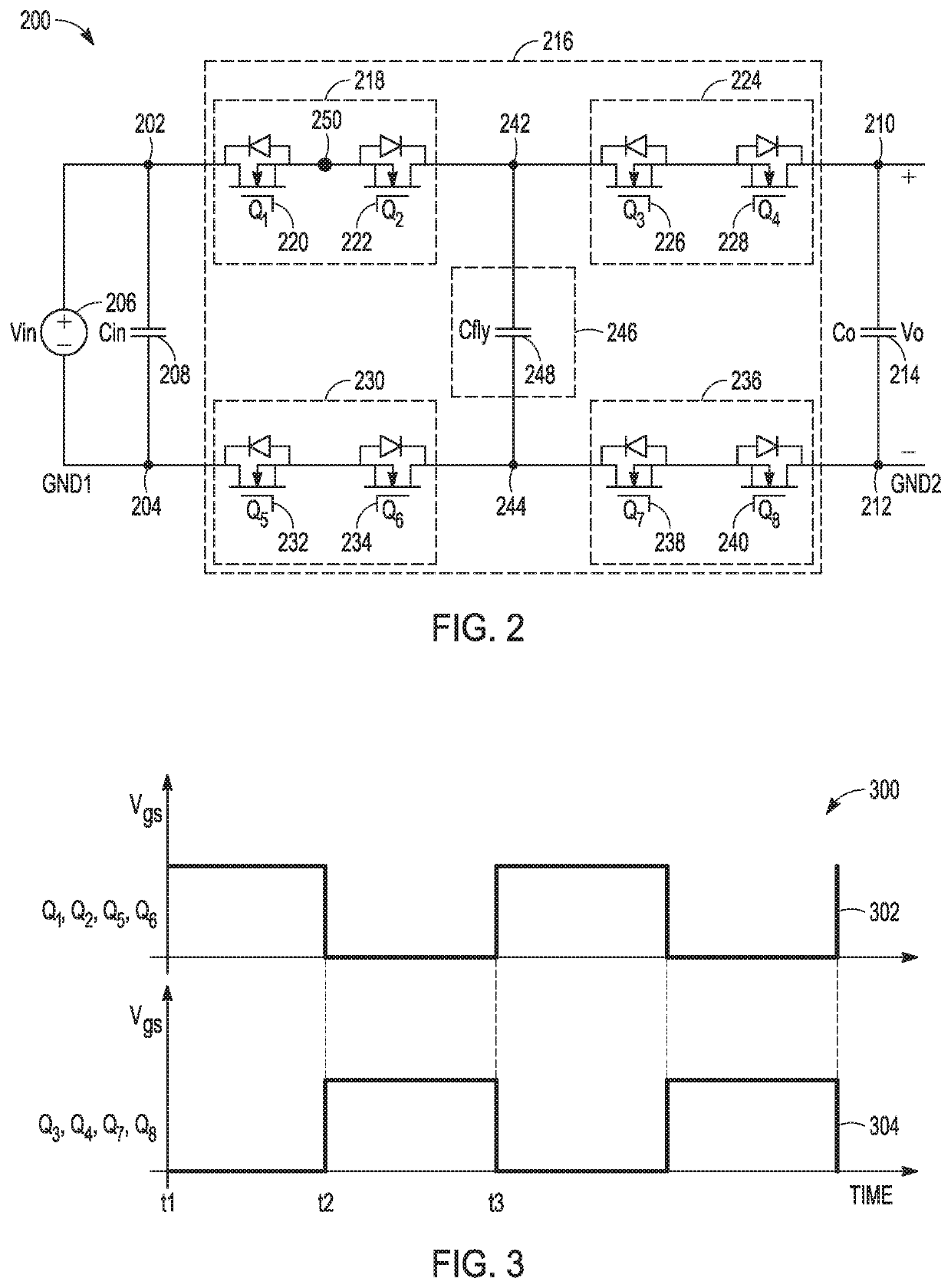
The present invention provides a power converter circuit that can isolate different power domains without using a transformer. This circuit includes an energy-storage component and a network of FET assemblies to block current signaling. The invention allows for the continuous output of signals with low ripple and minimal output filtering. Additionally, the invention provides a solution to the problem of requiring a transformer in ground isolation circuits. The technical effects of the invention are a power converter circuit with improved isolation and a more efficient and flexible solution for providing ground isolation.

Problems solved by technology

In an example, the problem includes providing a converter with a non-inverting output using a minimum number of standard circuit components, and further includes providing a continuous output signal with low ripple and minimal output filtering.

Method used


Image

  • Switching converter for power domain separation
  • Switching converter for power domain separation
  • Switching converter for power domain separation

Examples


Embodiment Construction

[0020]Power systems can include one or more voltage or current converter circuits. A converter circuit can receive an electrical input signal having various input signal characteristics such as magnitude, frequency, and / or phase characteristics. In response to the input signal, the converter circuit can provide an electrical output signal, such as having characteristics that are similar to or different from those of the input signal.

[0021]Power systems can include one or more switches configured to adjust an output signal magnitude, frequency, reference level, and / or phase. Some power systems can include an isolation circuit, such as a transformer, to electrically isolate a converter output stage from a converter input stage using respective sides of the transformer.

[0022]Switched-mode converter circuits, or switching regulators, can provide power conversion, such as including output signal voltage or current regulation, such as using transistor switches that are either on or off. T...


PUM


Abstract

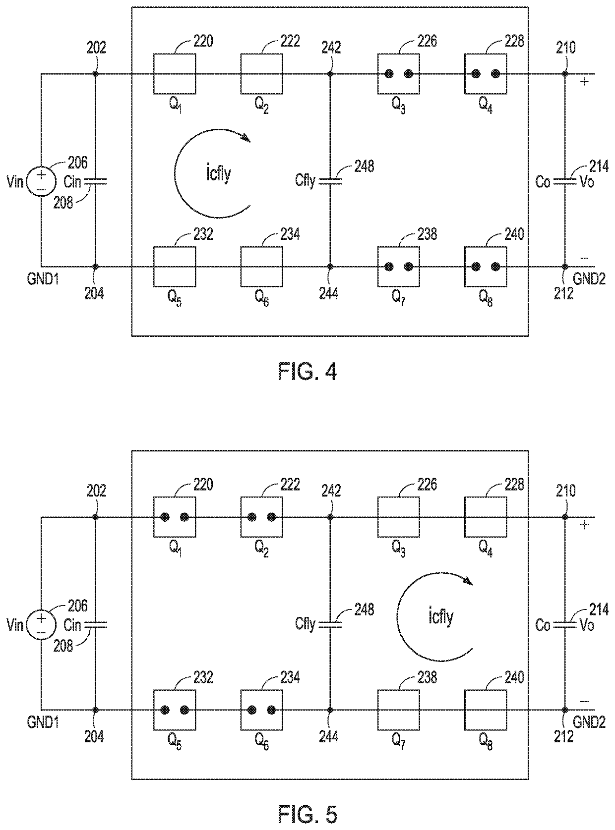
A power domain isolation system, such as without requiring a transformer, can include a reactive circuit, an input network having first and second input nodes that are coupled in parallel with the reactive circuit via respective first and second current control circuits, and an output network having first and second output nodes that are coupled in parallel with the reactive circuit via respective third and fourth current control circuits. The first and second current control circuits can be configured to couple the reactive circuit to the input nodes when the third and fourth current control circuits are configured to electrically isolate the reactive circuit from the output nodes, and the first and second current control circuits can be configured to electrically isolate the reactive circuit from the input nodes when the third and fourth current control circuits are configured to couple the reactive circuit to the output nodes.

Description

CROSS-REFERENCE TO RELATED APPLICATIONS[0001]This application is related to and claims priority to U.S. Provisional Application No. 62 / 876,366, filed on Jul. 19, 2019, and entitled “SWITCHED CAPACITOR CONVERTER FOR POWER GROUND SEPARATION,” the entirety of which is incorporated herein by reference.BACKGROUND[0002]A DC-DC power converter is a class of power converter used to convert a direct current (DC) signal from one voltage level to another, or to invert an input signal. Such a power converter is commonly used in electronic devices that are powered by regulated DC voltages. DC-DC converters can be particularly useful in applications with different sub-systems that can require or use different voltage input levels.[0003]Some DC-DC converters can include or use a magnetic energy storage mechanism, such as an inductor or transformer. The output voltage in such converters can be controlled by modulating a duty cycle of a signal used to charge the inductive component. Buck and boost c...

Claims


Application Information

Patent Timeline
Patent Type & Authority Applications(United States)
IPC IPC(8): H02M3/158H02M3/07
CPCH02M3/1584H02M2001/0025H02M3/07H02M3/158H02M1/0006H02M1/0025
Inventor FINGER, CHARLESLI, JIANSHI, ZHOUYUANZHANG, XU
Owner ANALOG DEVICES INT UNLTD
Learn More