Frequency detection to perform dynamic peak current control

a dynamic peak current and frequency detection technology, applied in the direction of electric variable regulation, instruments, power conversion systems, etc., can solve the problems of occupying more circuit space, affecting the power supply of components to be used, and affecting the power supply of components, so as to reduce the frequency of pulse width modulation power supply signals, the demand of load can be quickly and accurately determined, and the load is high. the effect of power supply

Active Publication Date: 2018-06-26
STMICROELECTRONICS ASIA PACIFIC PTE
View PDF2 Cites 1 Cited by
  • Summary
  • Abstract
  • Description
  • Claims
  • Application Information

AI Technical Summary

Benefits of technology

[0003]According to principles of the various embodiments discussed herein, a new technique is proposed to managing and controlling the peak current that will be output by a power supply. An entire new technique for sensing the power drawn by the load and varying the peak amount of current that will be permitted is introduced. In particular, the amount of power being output to the load is sensed by sampling the frequency of the pulse width modulation signal that is controlling the switch that is providing the power to the load. If the pulse width modulation signal has a high frequency, then it will be providing higher power to the load. As the power drawn by the load decreases, the frequency of the pulse width modulation power supply signal will decrease. By sensing and periodically sampling the frequency of the pulse width modulation signal that is providing power, the demand of the load can be quickly and accurately determined.
[0004]A circuit which makes use of sampling the output frequency of a variable frequency mode switching regulator permits the use of the circuit in which the peak current that is permitted by the system can be adjusted adaptively. Namely, the peak current that the circuit is permitted to output can vary, depending on the power being drawn by the load, to adaptively provide the most efficient operating frequency. This will improve dynamic transient load responses, provide a higher efficiency of operation, as well as generally resulting in a higher operating frequency for the output of the power to the load. Using such an adaptive, dynamically variable peak current regulator, the maximum peak current that can be reached by the system can be limited to an overall lower current and further, the amount of time that the circuit operates in a low current mode will be increased. This will permit the use of smaller components, such as a smaller inductor, and transistors which can have a lower current rating. Such a circuit will save costs in the construction and have a lower overall power dissipation for the switching regulator as it provides power to the load.
[0010]Using this method of controlling the switching voltage regulator, there is no need to sense the output voltage in order to determine the bias current that is needed or if the peak current is being approached. The circuit response to transients, such as high or low power conditions will be very fast, resulting in low ripples in the power supply output. The operating frequency of the PWM output system will, therefore, be much faster and usually higher than under prior art systems. Accordingly, in the present system there is a tracking timer that is used to reset the integrator. When the operating period is longer than the timer period, the hold capacitor is reset. This will significantly improve the output recovery from a maximum load a light load condition by resetting the current limit to a new minimum as the power drawn by the load is varied. This permits the maximum peak current that the system may experience at any one time to be limited to different values which are dynamically changed based on the amount of power drawn by the load. In addition, there will be a minimum value that the peak current can be limited to in order to ensure continued operation, even during very low power draw situations.

Problems solved by technology

One of the issues that must be addressed in a DC-DC switching regulator is the power ratings of the components to be used in the circuit.
In particular, if a component, such as a transistor, inductor, or the like has a high current rating, it will generally be more robust, but will also be larger, significantly more expensive, and take up more space in the circuit.
As can be appreciated, if components, such as transistors and inductors having a low current rating, are subjected to a current that exceeds their ratings they may be harmed, or even destroyed, thus preventing proper operation of the circuit.

Method used


Image

  • Frequency detection to perform dynamic peak current control
  • Frequency detection to perform dynamic peak current control
  • Frequency detection to perform dynamic peak current control

Examples


Embodiment Construction

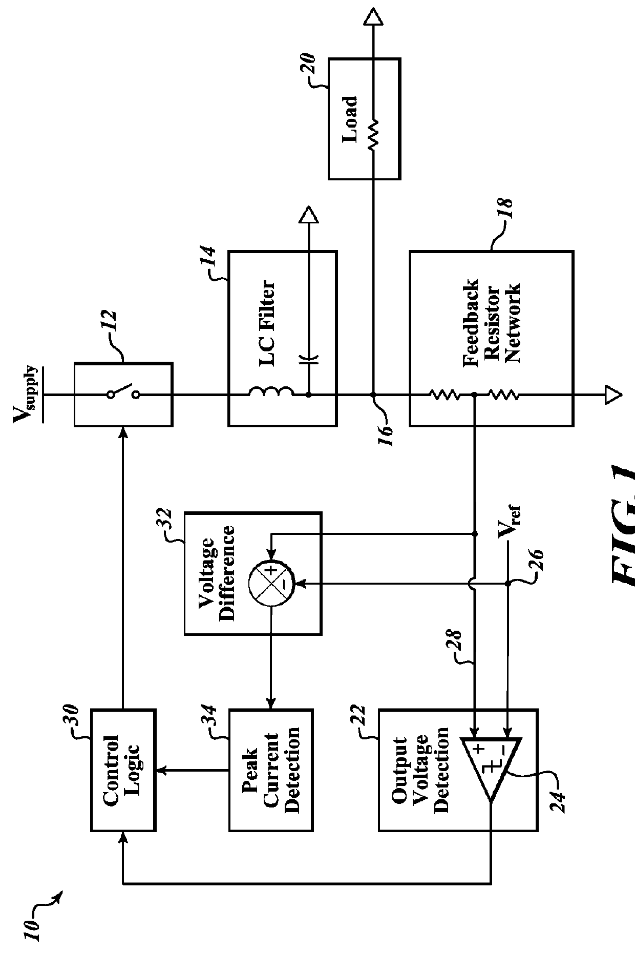
[0019]FIG. 1 illustrates a DC-DC switching regulator 10 of a type known in the prior art. As can be seen in this prior art circuit, a power switch 12 provides input power to drive a load 20. The power provided through the power switch 12 passes through an LC filter 14 before being available to the load. The load is connected to node 16 to receive the power that is output from the LC filter 14. A feedback resistor network 18 is coupled to node 16 in order to sense the amount of power drawn by the load. In this particular prior art system 10, the feedback resistor network 18 provides one input to an output detection circuit 22. In this particular output detection circuit 22, a comparator 24 is provided which receives a reference voltage 26 on the inverting input and the feedback voltage 28 on the noninverting input.

[0020]The output of the output detection voltage detection stage 22 is provided to the control logic 30 which controls the switching of the power supply switch 12. If the o...


PUM


Abstract

The amount of power being output to the load is sensed by sampling the frequency of the pulse width modulation signal that is controlling the switch that is providing the power to the load. If the pulse width modulation signal has a high frequency, then it will be providing higher power to the load. As the power drawn by the load decreases, the frequency of the pulse width modulation power supply signal will decrease. By sensing and periodically sampling the frequency of the pulse width modulation signal that is providing power, the demand of the load can be quickly and accurately determined. As the power demand of the load decreases, the peak current that the power supply switch can provide also decreases. The permitted peak current dynamically changes to adapt to the power drawn by the load.

Description

BACKGROUNDTechnical Field[0001]This invention is in the field of switching regulators and, in particular, a circuit which adaptively controls, to varying levels, the maximum current that can be supplied from the regulator.Description of the Related Art[0002]Inductive DC-DC switching power supply regulators are known in the art to be efficient power stage converters to provide different voltages within a system. Such a DC-DC switching regulator uses an external inductor as a storage device to transform a voltage level from one voltage to another or, transition from a voltage-based power output to a current-based power output. There are many types of switching regulators, ranging from buck regulators, buck-boost regulators, boost regulators, and the like. These may operate in either continuous or discontinuous mode. Some of these regulators have a fixed frequency, while others have a variable frequency that can depend on the application and the external components that can be selected...

Claims


Application Information

Patent Timeline
Patent Type & Authority Patents(United States)
IPC IPC(8): H02M3/158H02M1/088H02M1/00
CPCH02M3/158H02M1/088H02M2001/0009H02M1/32H02M3/156H02M3/1566H02M1/0019H02M1/0009
Inventor LEONG, KONG YIN
Owner STMICROELECTRONICS ASIA PACIFIC PTE
Why Eureka
Try Eureka