Ceramic discharge lamp with integral burner and reflector
a technology of ceramic discharge lamp and burner, which is applied in the manufacture of electric discharge tubes/lamps, lighting and heating apparatus, and electric discharge systems. it can solve the problems of less than satisfactory attempts to combine the integral short arc features of cermax® lamps with a filling that remains unobtrusive during operation
- Summary
- Abstract
- Description
- Claims
- Application Information
AI Technical Summary
Benefits of technology
Problems solved by technology
Method used
Image
Examples
first embodiment
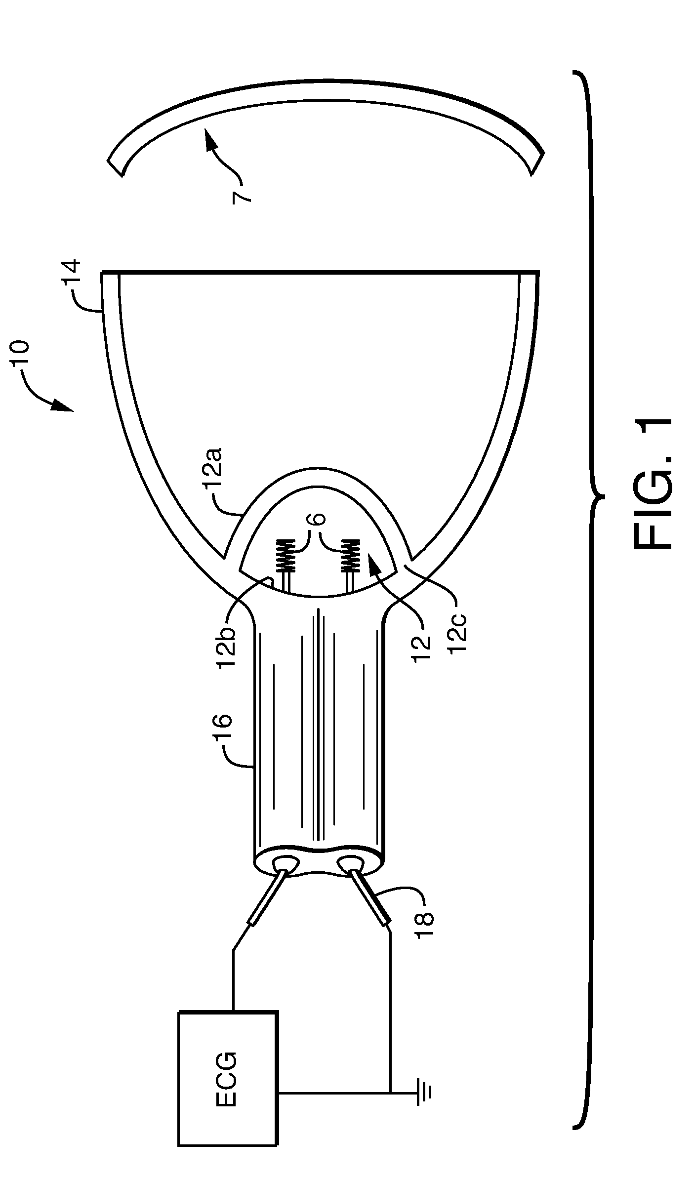
[0022]A more complete description is afforded by inspection of the drawings. FIG. 1 shows the lamp of the present invention. The geometry of an elliptical reflector suitable for the present invention is shown in FIG. 6. The lamp 10 includes a ceramic discharge chamber 12 that is positioned so the arc is at focus F′ of ceramic reflector 14. The reflector 14 collects the light from the discharge chamber 12 and focuses it to F. A ceramic capillary 16 is provided and includes two electrodes 18 that extend into the discharge chamber so that an imaginary line between the tips 6 of the electrodes intersects the focus F′. The discharge chamber 12 includes two concave parts 12a and 12b (right and left parts of the chamber 12 in FIG. 1) attached to each other at a seam 12c, where the ceramic reflector 14 is directly attached to an exterior surface of the discharge chamber 12 at the seam 12c, such as shown in FIG. 1. Preferably, the concave parts are generally hemispherical. Generally hemisphe...
second embodiment
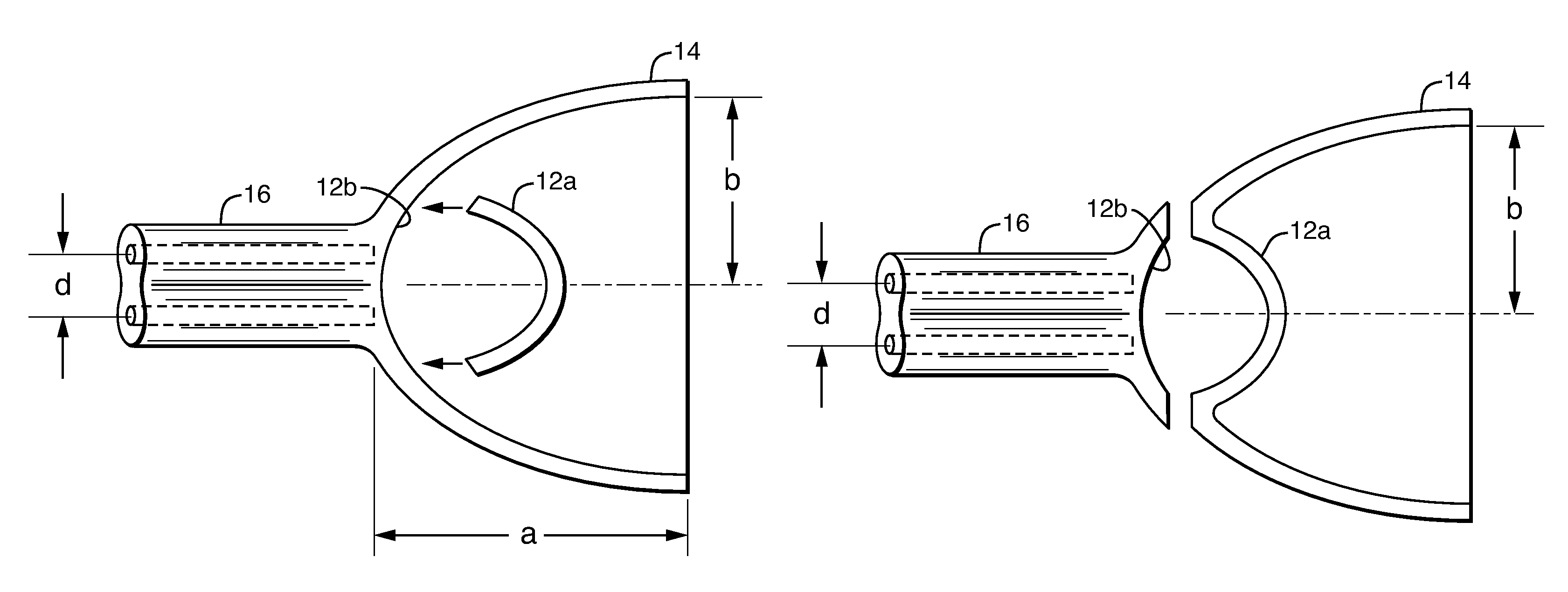
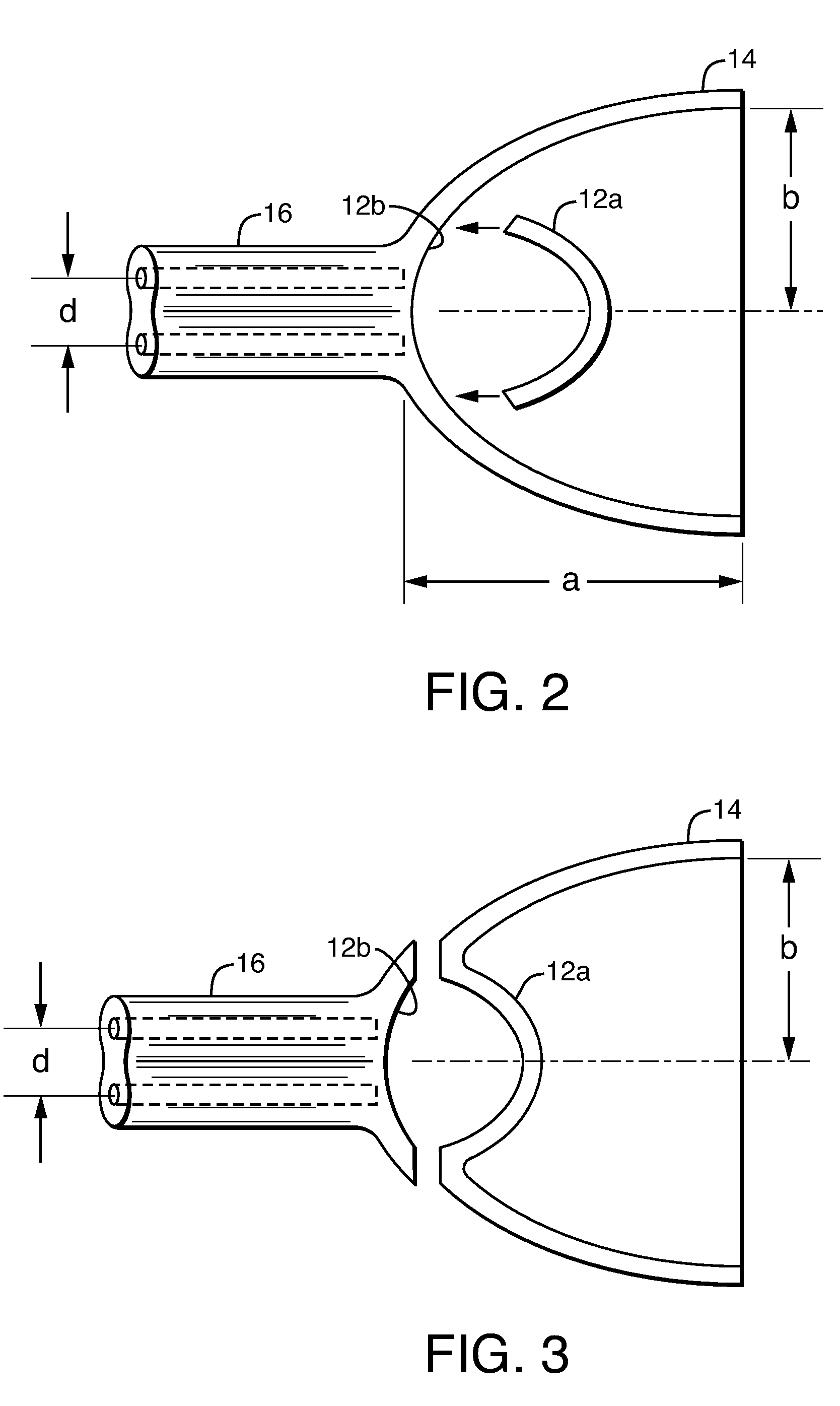
[0027]If the desired discharge cavity volume and placement at the focal point of the reflector are not compatible with the shape shown in FIG. 1 (for example, operation at lower wattage requires a smaller discharge volume), the discharge cavity 12 can be produced as a small isolated cavity positioned further inside the reflector 14 as shown in FIG. 4. This allows maximum flexibility in controlling discharge cavity volume and focal position. This configuration could be produced by using three ceramic shapes as shown in FIGS. 5a, b and joined together to form the final component. As shown in FIG. 5a, the capillary component may first be joined to the portion completing the closure of the discharge cavity using thermal or chemical joining. The reflector could then be slid onto the capillary portion as shown in FIG. 5b. The bonding of the reflector to the capillary portion could be done in the green state by thermal or chemical joining, in the pre-fired state using an interference fitti...
PUM
| Property | Measurement | Unit |
|---|---|---|
| pressure | aaaaa | aaaaa |
| pressure | aaaaa | aaaaa |
| angle | aaaaa | aaaaa |
Abstract
Description
Claims
Application Information
 - R&D
- Intellectual Property
- Life Sciences
- Materials
- Tech Scout
- Unparalleled Data Quality
- Higher Quality Content
- 60% Fewer Hallucinations
Browse by: Latest US Patents, China's latest patents, Technical Efficacy Thesaurus, Application Domain, Technology Topic, Popular Technical Reports.
© 2025 PatSnap. All rights reserved.Legal|Privacy policy|Modern Slavery Act Transparency Statement|Sitemap|About US| Contact US: help@patsnap.com


