A kind of convective heat sink and its manufacturing method

A heat sink and heat pipe technology, which is applied in the field of convection heat sink and its production, can solve the problem of large unit power load, etc., and achieve the effect of large power load, good density consistency, and simple manufacturing process

Active Publication Date: 2018-11-13
世保康环境电器(南京)有限公司
View PDF6 Cites 0 Cited by
  • Summary
  • Abstract
  • Description
  • Claims
  • Application Information

AI Technical Summary

Problems solved by technology

The external unit has a large power load

Method used


Image

  • A kind of convective heat sink and its manufacturing method
  • A kind of convective heat sink and its manufacturing method
  • A kind of convective heat sink and its manufacturing method

Examples


Embodiment Construction

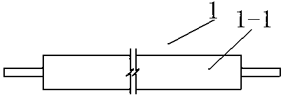
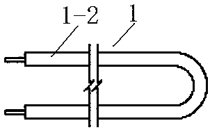
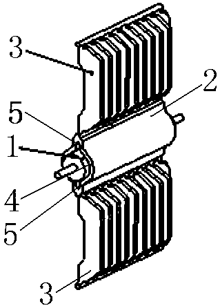
[0023] Refer to attached Figure 1~5 , a convection radiator includes a heat pipe 2, a heat sink 3 and an electric heating pipe 1. Heat pipe 2 is provided with electric heating pipe installation hole 4, heat pipe installation hole 4 is provided with shrinkage joint (groove) 5, electric heat pipe 1 is installed in electric heat pipe installation hole 4, and heat dissipation pipe 2 is equipped with heat sink 3 outside, heat sink 3 There are compensation shrinkage joints. The heat sink 3 adopts guide fins.

[0024] Radiating fins 3 are distributed symmetrically on the outside of the heat pipe 2 . See attached image 3 .

[0025] The heat sink 3 adopts the guide fins made up and down of the heat pipe. See attached image 3 .

[0026] Compensating shrinkage joints 6 are left in the longitudinal direction of the heat sink 3 . See attached Figure 4 .

[0027] The compensation shrinkage joint 6 is provided with openings, and the openings are in staggered directions, or in t...


PUM


Abstract

The invention relates to a counter flow type radiator and a manufacturing method thereof. The structure is particularly suitable for devices with ordinary heating requirements. The counter flow type radiator comprises a cooling pipe, cooling fins and an electric heat pipe. The cooling pipe is provided with an electric heat pipe installing hole. Shrinkage joints are arranged in the cooling pipe installing hole. The electric heat pipe is installed in the electric heat pipe installing hole. The cooling fins are arranged outside the cooling pipe. Compensation shrinkage joints are reserved in the cooling fins. The manufacturing method of the counter flow type radiator comprises the steps that firstly, an aluminum sectional bar is adopted to be machined into the cooling pipe, the electric heat pipe installing hole is reserved in the middle of the cooling pipe, and the shrinkage joints are reserved in the electric heat pipe installing hole; secondly, the cooling fins are manufactured above and below the cooling pipe, and the compensation shrinkage joints are reserved in the length direction of the cooling fins; and thirdly, the electric heat pipe is installed and installed in the electric heat pipe installing hole in the middle of the cooling pipe, the electric heat pipe and the electric heat pipe installing hole are in close contact evenly through compression, a compression die is used through a press, the electric heat pipe installing hole formed in the middle of the cooling pipe is pressurized and wraps an electric heat pipe body, the electric heat pipe body and the electric heat pipe installing hole are in close contact evenly through compression, and the counter flow type radiator is manufactured.

Description

technical field [0001] The invention relates to a convection radiator and a manufacturing method thereof, and the structure is especially suitable for devices requiring general heating. Background technique [0002] At present, it is difficult for various single-fin and multi-fin heat sinks to pass through the heating wire to fill the powder, the diameter of the tube cannot be uniformly shrunk, and the heat-conducting insulating powder in the tube cannot be compressed to the process requirements, the density consistency is poor, and the external unit power load is small. There are many manufacturing processes and the process method is complicated. Moreover, there are many manufacturing processes for the heat sink body, and the process method is complicated. Another example is the combination of piercing methods, and the connection between the electric heating tube and the heat sink is not tight. The thermal conductivity is weakened and the processing is complicated. In ad...

Claims


Application Information

Patent Timeline
Patent Type & Authority Patents(China)
IPC IPC(8): F24D13/02F24D19/00
Inventor 张翼鹏沈森华曲云发
Owner 世保康环境电器(南京)有限公司
Why Eureka
Try Eureka