
Evaporative thermal management of grazing incidence collectors for EUV lithography

a collector and evaporative thermal management technology, applied in the field of grazingincidence collectors, can solve the problems of increasing the thermal load on the gic, compromising uniformity, and substantial thermal load on the one or more gic mirror shells, so as to minimize thermal distortion of the optical surface and uniform temperature distribution

Active Publication Date: 2014-05-20
MEDIA LARIO SRL
View PDF47 Cites 0 Cited by
  • Summary
  • Abstract
  • Description
  • Claims
  • Application Information

AI Technical Summary

Benefits of technology

[0008]The disclosed systems for and methods of evaporative thermal management of GIC mirror systems allow cooling under high power loading conditions associated with actual commercial EUV lithography without requiring complex, high-volume plumbing of coolant to the GIC mirrors. The disclosed systems also allow for maintaining a substantially uniform temperature distribution over a large area optical surface, which serves to minimize thermal distortion of the optical surface.
[0009]A particular advantage of the evaporative approaches disclosed is that the cooling process is self-regulating; that is, areas of the optical structure that have higher power loading will tend to get warmer, thereby leading to a higher rate of evaporation and therefore a higher cooling rate.
[0011]The heat-pipe configuration provides substantially uniform cooling of the GIC mirror shell over the entire GIC mirror shell while avoiding spatial modulations of the GIC mirror reflective surface that can occur when using networks of cooling lines in thermal contact with the GIC mirror shell. Moreover, the GIC evaporative thermal management systems and methods disclosed herein enable efficient cooling without the need for flowing large amounts of coolant at relatively high flow rates. Further, the evaporative thermal management systems and methods can be implemented in embodiments that add only a few millimeters of width to the GIC mirror shell. This results in a low-profile design that allows for a nested GIC mirror shell configuration with minimal obscuration of the optical pathways between the EUV radiation source and the intermediate focus.

Problems solved by technology

This broadband radiation causes a substantial thermal load on the one or more GIC mirror shells.
This requires a specified degree of radiation uniformity in the far field of the GIC radiation pattern, and this uniformity can be compromised by distortion or figure errors in the GIC mirror shells.
In fact, the increasing demand for higher EUV power in such commercial systems also increases the thermal load on the GIC.

Method used


Image

  • Evaporative thermal management of grazing incidence collectors for EUV lithography
  • Evaporative thermal management of grazing incidence collectors for EUV lithography
  • Evaporative thermal management of grazing incidence collectors for EUV lithography

Examples


example gic

Mirror Cooling Assembly Parameters

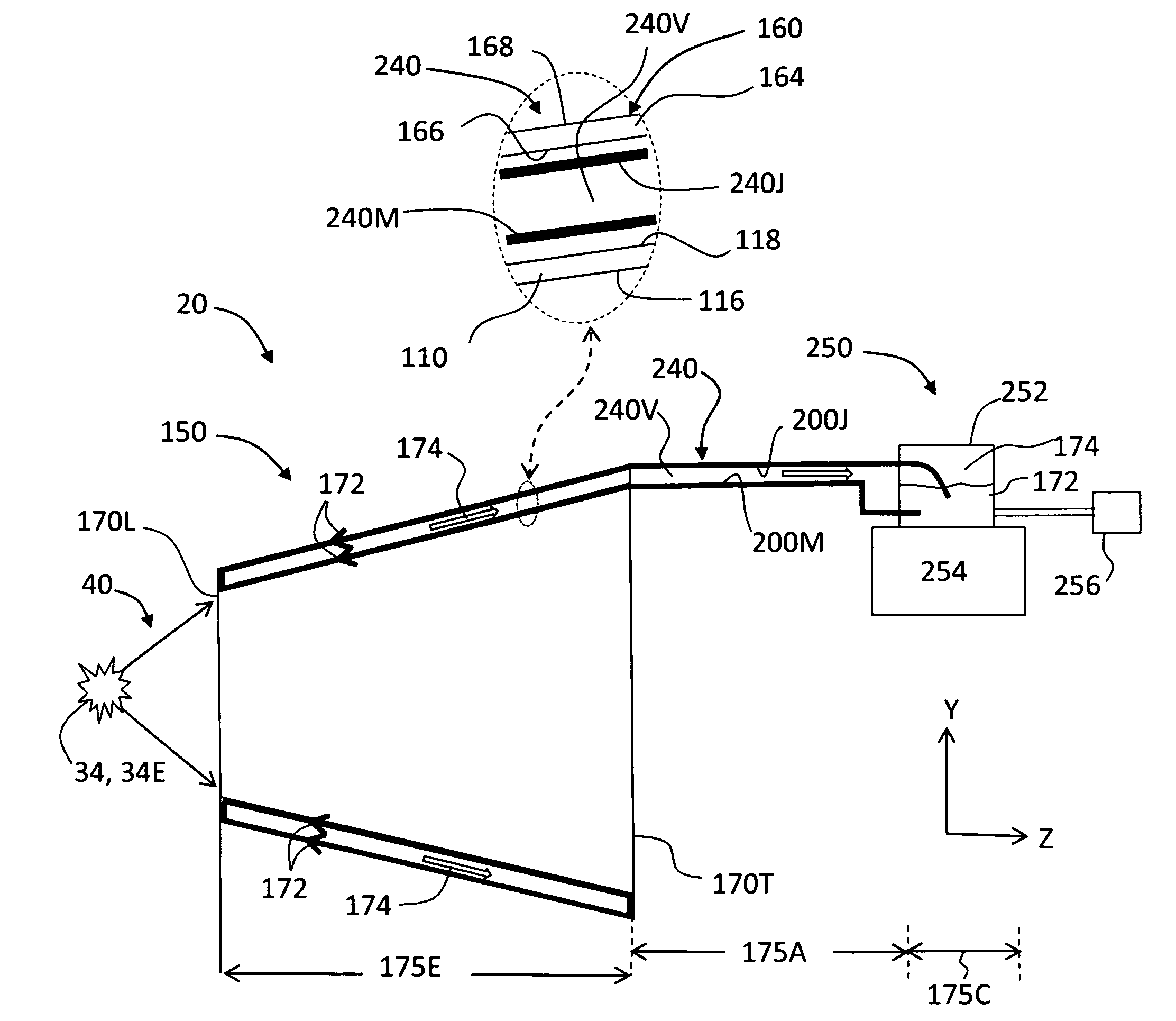
[0092]FIG. 19 is similar to FIG. 10 and is used to illustrate an example embodiment of GIC mirror cooling assembly 150 that illustrates an example set or range of design parameters that satisfy the key operational parameters (namely, the capillary, sonic, entrainment, and boiling limits) associated with a heat-pipe thermal management configuration such as used in the GIC mirror cooling assembly.

[0093]In FIG. 9 the direction of gravity G is shown in an example direction to indicate that gravitational assist occurs when the direction of G has a component in the direction of the capillary flow of cooling fluid 172. Other directions for gravity G are possible that have a component in the direction of capillary flow of cooling fluid 172.

[0094]In GIC mirror cooling assembly 150, GIC mirror assembly 100 defines evaporation region 175E. It is assumed that wicks 240M and 240J have a thickness of 1 mm and the width of the vapor channel 240V in chamber 180 is ...


PUM


Abstract

Evaporate thermal management systems for and methods of grazing incidence collectors (GICs) for extreme ultraviolet (EUV) lithography include a GIC shell interfaced with a jacket to form a structure having a leading end and that defines a chamber. The chamber operably supports at least one wicking layer. A conduit connects the wicking layer to a condenser system that support cooling fluid in a reservoir. When heat is applied to the leading end, the cooling fluid is drawn into the chamber from the condenser unit via capillary action in the wicking layer and an optional gravity assist, while vapor is drawn in the opposite direction from the chamber to the condenser unit. Heat is removed from the condensed vapor at the condenser unit, thereby cooling the GIC mirror shell.

Description

CLAIM OF PRIORITY[0001]This application claims the benefit of priority under 35 U.S.C. §119(e) of U.S. Provisional Patent Application Ser. No. 61 / 518,378, filed on May 4, 2011, which application is incorporated by reference herein.FIELD[0002]The present invention relates generally to grazing-incidence collectors (GICs), and in particular to systems and methods of evaporative thermal management of GICs used in extreme ultraviolet (EUV) lithography.BACKGROUND ART[0003]EUV lithography is anticipated to be the lithographic process of choice for producing future generations of semiconductor devices having line widths on the order of 27 nm and smaller. The wavelength of the EUV radiation is nominally 13.5 nm, which calls for the use of specialized optics to collect and image the EUV radiation.[0004]One type of EUV optical system used to collect the radiation from the light source is a grazing incidence collector (GIC). A GIC typically comprises one or more concentrically arranged GIC mirr...

Claims


Application Information

Patent Timeline
Patent Type & Authority Patents(United States)
IPC IPC(8): H05G1/02G21K1/06G02B5/08G02B7/195H01J35/16
CPCG03F7/70166F28D15/046F28D15/04G02B7/1815F28D15/0266F28D15/0208F28D15/043G21K1/067H05G2/001G21K1/06G03F7/70891
Inventor GREK, BORISSTEARNS, DANIELCEGLIO, NATALE M.
Owner MEDIA LARIO SRL
Learn More