
A charging and discharging control system and method

A charging and discharging control and controller technology, applied in the direction of AC network load balancing, etc., can solve problems such as waste of electric energy, low efficiency, grid pollution, etc., and achieve the effect of reducing technical difficulty and cost, reducing cost, and improving efficiency

Active Publication Date: 2017-10-31
西安迅湃快速充电技术有限公司
View PDF3 Cites 0 Cited by
  • Summary
  • Abstract
  • Description
  • Claims
  • Application Information

AI Technical Summary

Problems solved by technology

This method has obvious disadvantages. For a large-capacity battery or capacitor that is fully charged, it takes a long time to discharge it when it is connected to a load. The next round of charge-discharge test will significantly reduce the test efficiency, and let the load absorb energy. A large amount of electric energy is wasted, and the next round of charging and discharging tests still needs to be powered from the grid. This test method is very costly
On the other hand, during the discharge test, although the charge of the battery or capacitor can be returned to the grid, improper handling may bring "pollution" to the grid. In severe cases, electrical equipment and power facilities may be damaged due to grid voltage fluctuations
The traditional method has the problem of low efficiency due to the lack of quantitative analysis of charging and discharging

Method used


Image

  • A charging and discharging control system and method
  • A charging and discharging control system and method
  • A charging and discharging control system and method

Examples


Embodiment Construction

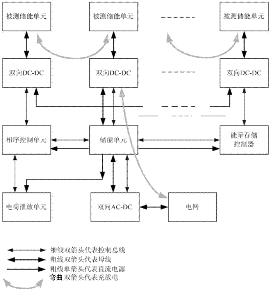
[0036] Such as figure 1As shown, the charging and discharging control system of the present invention includes a plurality of bidirectional DC-DCs, a phase sequence control unit, an energy storage unit, an energy storage controller, a charge discharge unit, a bidirectional AC-DC and connecting the above-mentioned components The bus bar; wherein, the input end of each bidirectional DC-DC is connected to the bus bar so that all bidirectional DC-DCs form a cascade system; each bidirectional DC-DC is connected to the phase sequence control unit, energy storage unit and Energy storage controller; the control bus is composed of address lines and data lines; both the phase sequence control unit and the energy storage controller are connected to the energy storage unit through the control bus and DC power line; the energy storage unit and the bidirectional AC-DC are connected through the bus and control bus Connection; bidirectional AC-DC is connected to the grid through the busbar. ...


PUM


Abstract

The invention discloses a charging and discharging control system, which includes multiple bidirectional DC-DCs, a phase sequence control unit, an energy storage unit, an energy storage controller, a charge discharge unit and a bidirectional AC-DC; Charge and discharge control method: the phase sequence control unit detects whether the bidirectional DC-DC is installed in place; the energy storage controller controls the bidirectional DC-DC to sample the voltage of the energy storage unit under test, and the phase sequence control unit checks the working status of each bidirectional DC-DC Make settings; the energy storage controller samples and monitors the bus voltage and current to determine whether the voltage meets the requirements. If it does not meet the requirements, the phase sequence control unit adjusts the bidirectional DC- The number of DCs and the number of bidirectional DC-DCs in the discharge state until they meet the requirements. The invention greatly improves the charging and discharging test efficiency of the tested energy storage unit, reduces the cost of the tested unit's charging and discharging test, minimizes the impact on the power grid, and has high safety.

Description

technical field [0001] The invention belongs to the technical field of charging, and in particular relates to a charging and discharging control system and method. The invention is suitable for switching power supply circuits. Background technique [0002] In the production process of batteries or capacitors, it is often necessary to perform charge and discharge tests on batteries or capacitors to test parameters such as battery or capacitor capacity, charge and discharge time, and current. The traditional charging test method is to use bidirectional AC-DC (Dual Alternate Current to Direct Current Convertor), which takes power from the grid to convert AC to DC, and then converts it to the charging voltage allowed by the battery or capacitor through bidirectional DC-DC for charging and discharging. During the test, the charge of the battery or capacitor is absorbed by the bidirectional DC-DC and then connected to the load, or this part of the charge is further processed by t...

Claims


Application Information

Patent Timeline
Patent Type & Authority Patents(China)
IPC IPC(8): H02J3/32
Inventor 蔡晓卢军毛建华石永星
Owner 西安迅湃快速充电技术有限公司
Learn More