Power supply device

a power supply device and power supply technology, applied in the field of power supply devices, can solve the problems of high ripple factor of output current after rectifier, inability to control resonant converters through frequency modulation, and difficulty in controlling parallel-connected resonant converters to and achieve low ripple and uniform current output

Active Publication Date: 2011-09-20
LITE ON ELECTRONICS (GUANGZHOU) LTD +1
View PDF1 Cites 2 Cited by
  • Summary
  • Abstract
  • Description
  • Claims
  • Application Information

AI Technical Summary

Benefits of technology

[0010]Therefore, an object of the present invention is to provide a power supply device capable of achieving low ripple and uniform current output.

Problems solved by technology

Nevertheless, because resonant converters operate on sinusoidal current waveforms, output current after rectifier always has high ripple factor.
However, resonant converters are controlled through frequency modulation and cannot be controlled through control technique of pulse-width-modulation (PWM) type DC / DC converters.
Therefore, control of parallel-connected resonant converters to achieve low ripple and uniform current output has been a difficulty.
Nonetheless, the conventional control method requires sampling of the output currents IOA, IOB of the first and second resonant circuits 91, 92, and is therefore difficult to implement.
Furthermore, the buck converter 94 reduces power conversion efficiency of the power supply device 900.
Moreover, the conventional control method requires that an optimal operating frequency (frequency at which gains of the first and second resonant circuits 91, 92 are substantially identical) be determined such that the output currents IOA, IOB are balanced, which can be difficult to achieve and is unfavorable in optimizing efficiency of the first and second resonant circuits 91, 92.

Method used


Image

  • Power supply device
  • Power supply device
  • Power supply device

Examples


Embodiment Construction

[0037]Before the present invention is described in greater detail, it should be noted that the same elements are denoted by the same reference numerals throughout the disclosure.

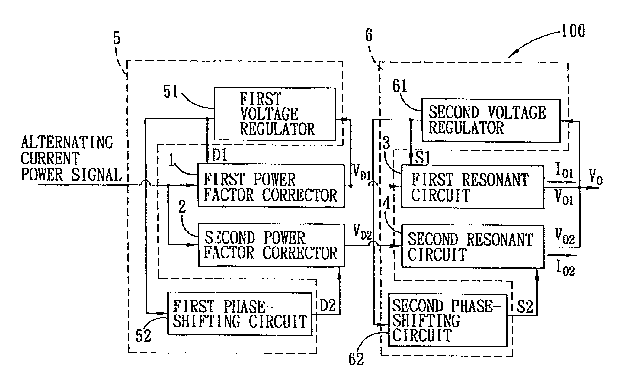
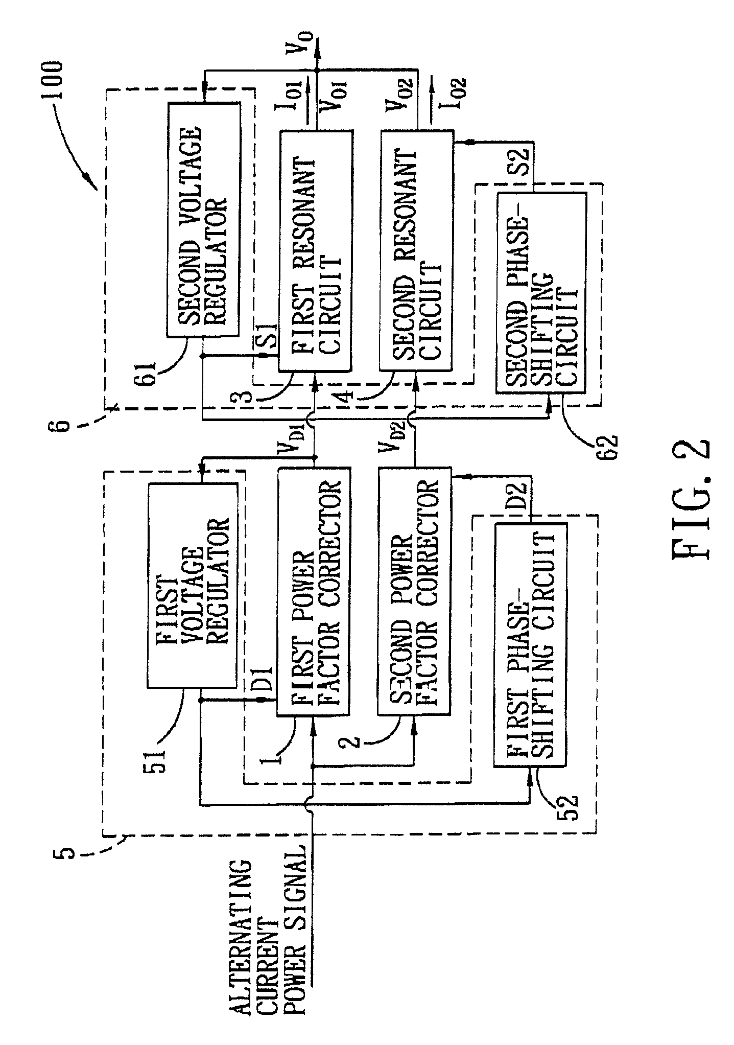
[0038]Referring to FIG. 2, a power supply device 100 of the first preferred embodiment of the present invention is capable of providing a stable output voltage VO and achieving a uniform current output. The power supply device 100 is used mainly in applications such as servers, workstations, telecommunication devices, desktop computers, gaming consoles, flat panel televisions, and distributed power systems. The power supply device 100 includes a first power factor corrector 1, a second power factor corrector 2, a first resonant circuit 3, a second resonant circuit 4, a current regulating circuit 5, and a voltage stabilizing circuit 6.

[0039]The first and second power factor correctors 1, 2 have input sides thereof coupled in parallel and receiving an alternating current (AC) input voltage. The AC input voltag...


PUM


Abstract

A power supply device includes first and second power factor correctors, and first and second resonant circuits. The first and second power factor correctors are for receiving an alternating current (AC) input voltage, and are driven by first and second driving signals for rectifying the AC input voltage to generate first and second driving voltages, respectively. The first and second resonant circuits are coupled to the first and second power factor correctors for receiving the first and second driving voltages, respectively, and have output sides that are coupled in parallel for outputting an output voltage. The first power factor corrector and the first resonant circuit in combination is parallel-connected to the second power factor corrector and the second resonant circuit in combination.

Description

CROSS-REFERENCE TO RELATED APPLICATION[0001]This application claims priority of Chinese Application No. 200910193158.4, filed on Oct. 15, 2009.BACKGROUND OF THE INVENTION[0002]1. Field of the Invention[0003]The present invention relates to a power supply device, more particularly to a power supply device that employs resonant converting circuits.[0004]2. Description of the Related Art[0005]Resonant converters are known to have advantages such as high conversion efficiency and low cost, and are hence commonly used in high-power isolated DC / DC conversion. Nevertheless, because resonant converters operate on sinusoidal current waveforms, output current after rectifier always has high ripple factor. Especially for applications that require high output power, a plurality of parallel-connected capacitors are required to meet requirements of ripple factor and voltage stress. Conventional technique for reducing ripple factor of LLC converters is to realize phase-shifting output currents of ...

Claims


Application Information

Patent Timeline
Patent Type & Authority Patents(United States)
IPC IPC(8): G05F5/00
CPCH02M1/4208H02M7/23Y02B70/126Y02B70/1441Y02B70/10
Inventor LI, MINGZHUZHAO, QINGLINYE, ZHIHONGZHANG, CHUNLINDING, XUEZHENG
Owner LITE ON ELECTRONICS (GUANGZHOU) LTD
Why Eureka
Try Eureka