
Amplifier device

a technology of amplifiers and amplifiers, applied in the direction of gain control, using reradiation, instruments, etc., can solve the problems of significant power loss in the energy supply device, and significant power loss in the amplifier circuit, so as to achieve cost-effective operation and small power loss. , the effect of small power loss

Inactive Publication Date: 2008-06-19
SIEMENS HEALTHCARE GMBH
View PDF4 Cites 3 Cited by
  • Summary
  • Abstract
  • Description
  • Claims
  • Application Information

AI Technical Summary

Benefits of technology

[0009]An object of the present invention is to further develop an amplifier device of the aforementioned type such that it can be manufactured and efficiently operated more cost-effectively. The amplifier device should in as a whole exhibit only a relatively small power loss.
[0011]Based on the inventive solution it is possible to connect the individual energy sources to the amplifier circuit without instabilities, clock couplings or even unwanted surprise effects being able to occur.
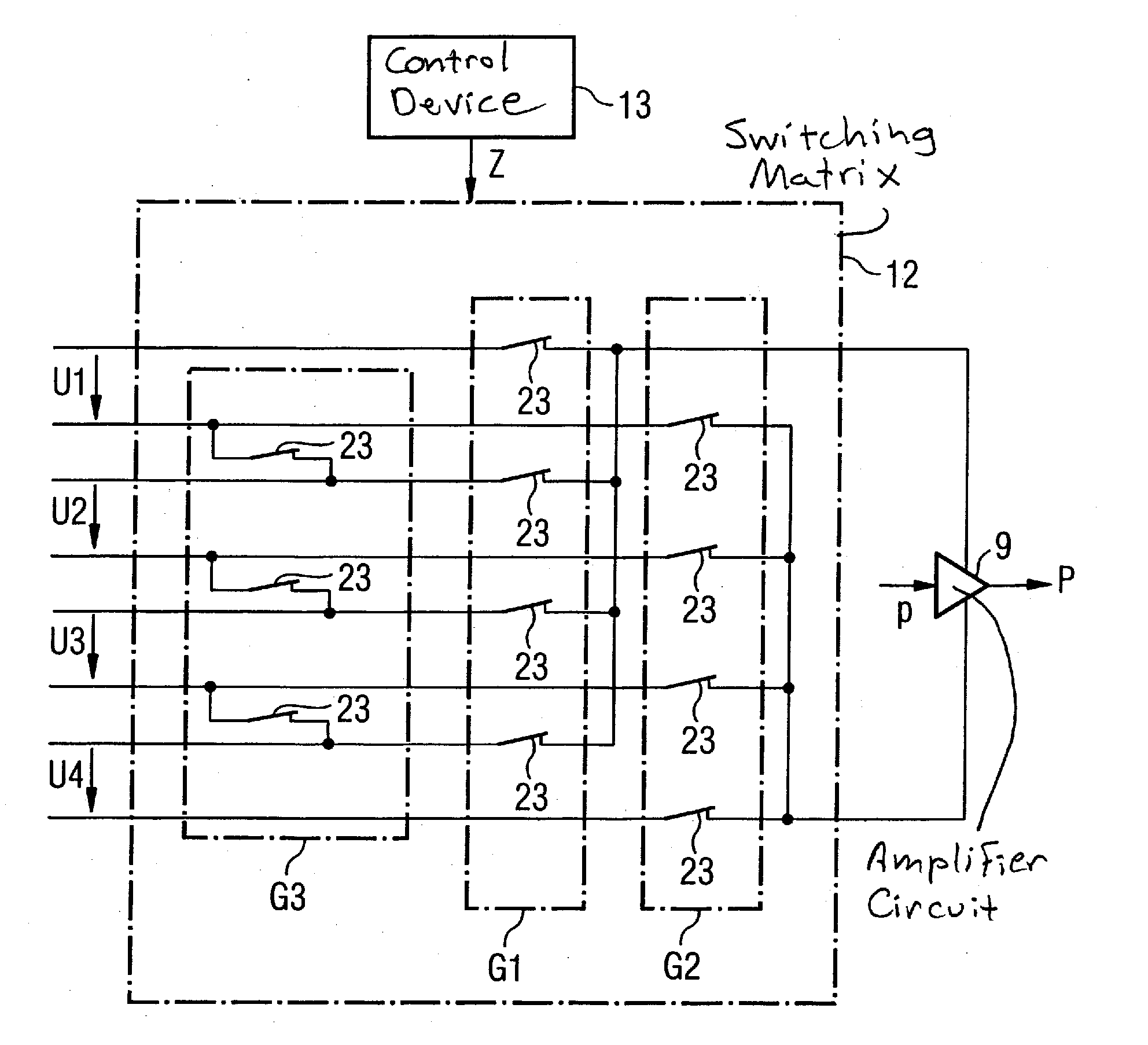
[0012]The switching matrix is advantageously fashioned and can be controlled by the control device such that at least one of the energy sources can be individually connected to the amplifier circuit. It is thereby possible to connect only one of the energy sources to the amplifier circuit at a specific point in time. Such a connection of a single energy source is particularly useful, when the power pulse to be output exhibits relatively low voltage and / or current requirements.
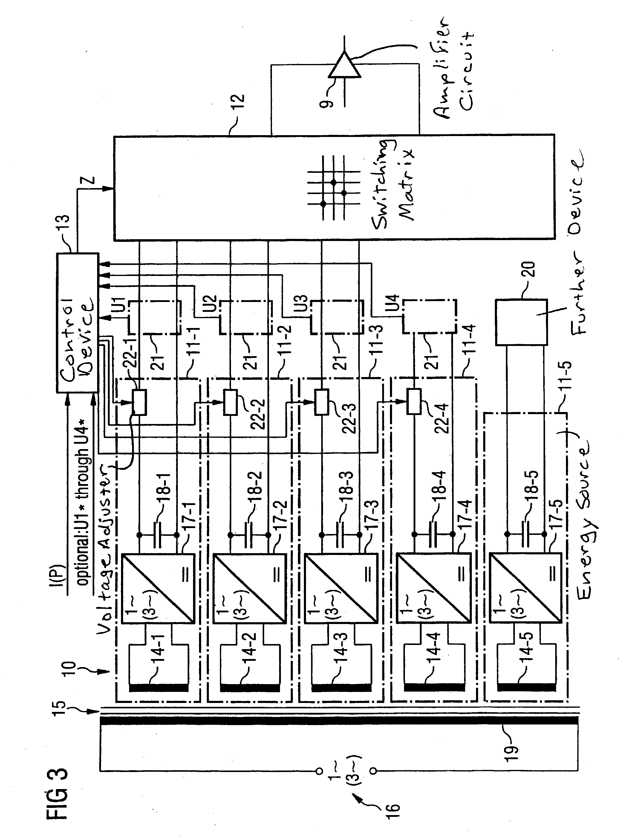
[0016]Each of the energy sources can advantageously be fed from an alternating voltage network (mains) via the secondary coil device of a transformer device (each energy source can have its own, individually associated secondary coil) and a rectifier device downstream of the respective secondary coil device. A potential isolation of the energy sources relative to one another this results in a particularly simple manner by this embodiment.
[0017]The transformer device is advantageously fashioned as a multi-phase (in particular three-phase) transformer device. A relatively low ripple of the direct voltage emitted by the energy sources thereby results in a simple manner.
[0018]The secondary coil devices advantageously interact with a single primary coil device that can be connected with the alternating voltage network. The design of the transformer device is simplified by this measure.

Problems solved by technology

In practice, however, this approach leads to significant power losses in the amplifier circuit in many operating situations.
The power losses are significantly higher than when the amplifier circuit is operated with voltage values that are adapted to the respective operating state of the amplifier circuit.
The adaptation of the voltage value leads to a reduction of the power loss that occurs in the amplifier circuit, but in many cases it leads to significant power losses in the energy supply device.
The problem is thus only shifted, and is not solved.

Method used


Image

  • Amplifier device
  • Amplifier device
  • Amplifier device

Examples


Embodiment Construction

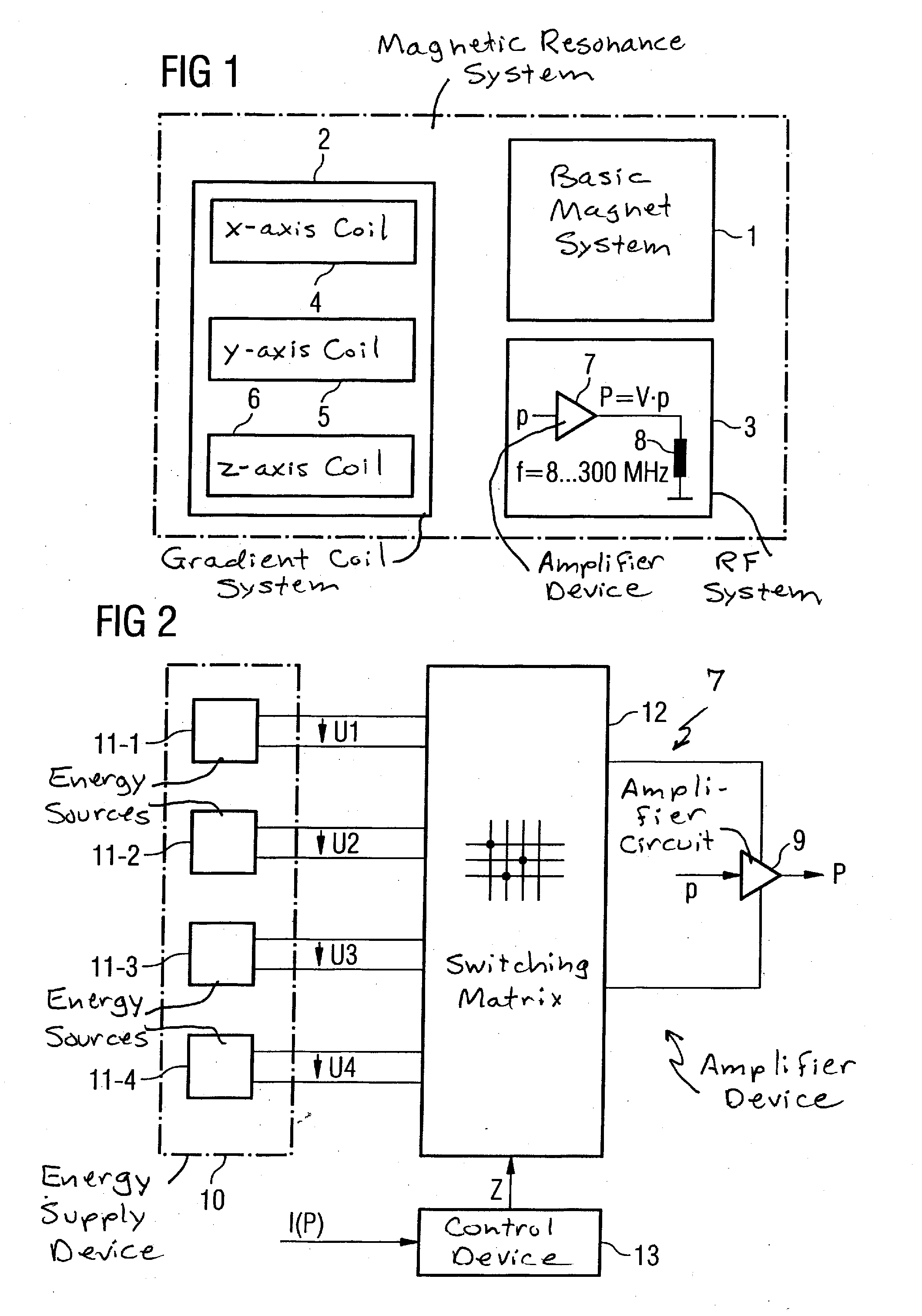
[0030]FIG. 1 shows an imaging magnetic resonance system with various coil systems namely a basic magnet system 1, a gradient magnet system 2 and a radio-frequency system 3. The gradient coil system 2 normally has three sub-systems 4, 5, 6, one for each of the three axes of a Cartesian coordinate system. The basic coil system 1 and the gradient magnet system 2 are of subordinate importance in the framework of the present invention and need not be explained in detail.

[0031]In the course of acquisition of a raw data sequence of the magnetic resonance system, a low-energy pulse (signal pulse) p is fed to an amplifier device 7 of the radio-frequency system 3 at specific points in time. Each low-energy pulse p exhibits a predetermined time curve that can be different from pulse p to pulse p. A longer pulse pause lies between every two low-energy pulses p. The amplifier device 7 amplifies the low-energy pulse p fed to it and thus generates a corresponding power pulse P. The amplifier devic...


PUM


Abstract

An amplifier device has an amplifier circuit, an energy supply device, a switching matrix and a control device. A radio-frequency, low-energy signal pulse can be amplified into a high-energy power pulse by the amplifier circuit. The amplifier circuit is supplied with electrical energy by the energy supply device. The energy supply device has a number of electrical energy sources that are separated in terms of potential relative to one another in a state in which they are not connected to the amplifier circuit. The electrical energy sources can be selectively connected to the amplifier circuit by the switching matrix. The switching state of the switching matrix can be dynamically set for this purpose by the control device.

Description

BACKGROUND OF THE INVENTION[0001]1. Field of the Invention[0002]The present invention concerns an amplifier device having an amplifier circuit and an energy supply device. A radio-frequency, low-energy signal pulse can be amplified into a power pulse by the amplifier circuit. The amplifier circuit is supplied with electrical energy by the energy supply device.[0003]2. Description of the Prior Art[0004]Amplifier devices of the above type are generally known. They are in particular used for generation of transmission pulses for RF transmission coils in magnetic resonance systems. Other applications, for example in radar systems, are also possible.[0005]In magnetic resonance systems the requirements for the power pulses to be output vary to a significant extent. This applies both for the duration of an individual pulse and for its maximum power and its average power as well as for the required currents and voltages.[0006]It is naturally possible to design the amplifier circuit and the ...

Claims


Application Information

Patent Timeline
Patent Type & Authority Applications(United States)
IPC IPC(8): H03F3/00
CPCH03F1/0244
Inventor ALBRECHT, ADAMKROECKEL, HORST
Owner SIEMENS HEALTHCARE GMBH
Learn More