RV converter with current mode and voltage mode switching

a current mode and voltage mode technology, applied in the direction of electric variable regulation, process and machine control, instruments, etc., can solve the problems of large power supply weight, inconvenient configuration of power converters with push-pull topology, and slow transient response of voltage controlled converters to input and output load changes, etc., to achieve better performance

Active Publication Date: 2007-08-02
SCHUMACHER ELECTRIC CORP
View PDF13 Cites 32 Cited by
  • Summary
  • Abstract
  • Description
  • Claims
  • Application Information

AI Technical Summary

Benefits of technology

[0015] Briefly, the present invention relates to a switched mode converter that includes both voltage mode and current mode control. The switched mode converter also includes mode logic for switching between a voltage mode and a current mode. The converter includes current sensing circuitry for sensing the switcher current on the primary side of the transformer and the load current on the secondary side as well as voltage sensing circuitry for sensing the converter output voltage. When the load current is less than a predetermined value, the converter operates in a voltage mode. During the voltage mode, the output voltage of the voltage mode controller is used to control the duty cycle of a pulse width modulation (PWM) controller. When the load current is greater than a predetermined value, the converter operates in a current mode. In a current mode, the primary switcher current is used to control the PWM controller. As such, during a light load in which the converter is voltage controlled, there is no need for a minimum load to stabilize the control loop. In a current-mode, the control loop will have a relatively faster transient response and avoid flux imbalance in push-pull topology. As such, the converter provides the advantages of both known voltage controlled and current controlled switched mode converters. In addition, by the careful arrangement of the locations of a EMC filter, a primary heat sink, a secondary heat sink, a power transformer T1 and other power devices as well as a cooling fan, a smaller EMC filter can be used due to the primary heat sink performing a dual function of thermal management and additionally providing EMC shielding to prevent the noise, for example, the noise generated by the transformer, from reaching the filter. In addition, the primary heat sink is configured to face the air flow while the secondary heat sink is placed close to the fan with its fin direction the same as the direction of the air flow. As such, both the primary and the secondary heat sink get maximum air flow, allowing smaller heat sinks to be used in order to provide a reliable and cost-effective switched mode converter.

Problems solved by technology

Although such linear power supplies are able to provide a fairly stable source of DC electrical power, such power supplies are relatively heavy, bulky and inefficient.
Unfortunately, such voltage controlled converters manifest a slow transient response to input and output load changes.
Moreover, such voltage controlled converters are generally not suitable for power converters configured with a push-pull topology due to the possible flux imbalance of the high frequency transformer.
Unfortunately, such current controlled switched mode converters have relatively poor output regulation compared to voltage controlled switched mode converters, especially during light load conditions.
In some applications, such as during conditions when the converter is connected to a battery as a load, the battery may be damaged and lose its recharge capability permanently due to it being discharged to an extreme low voltage for a long time by the minimum load when the input power to the converter is lost.
Another problem with such switched mode converters relates to electromagnetic compatibility (EMC) and thermal management.
In particular, even though such switched mode converters are relatively more efficient than linear power supplies, such switched mode converters are noisy due to the switching and thus can result in electromagnetic interference.
The power requirement of such loads is relatively substantial.
As such, such switched mode converters generate a significant amount of heat that must be dissipated.

Method used


Image

  • RV converter with current mode and voltage mode switching
  • RV converter with current mode and voltage mode switching
  • RV converter with current mode and voltage mode switching

Examples


Embodiment Construction

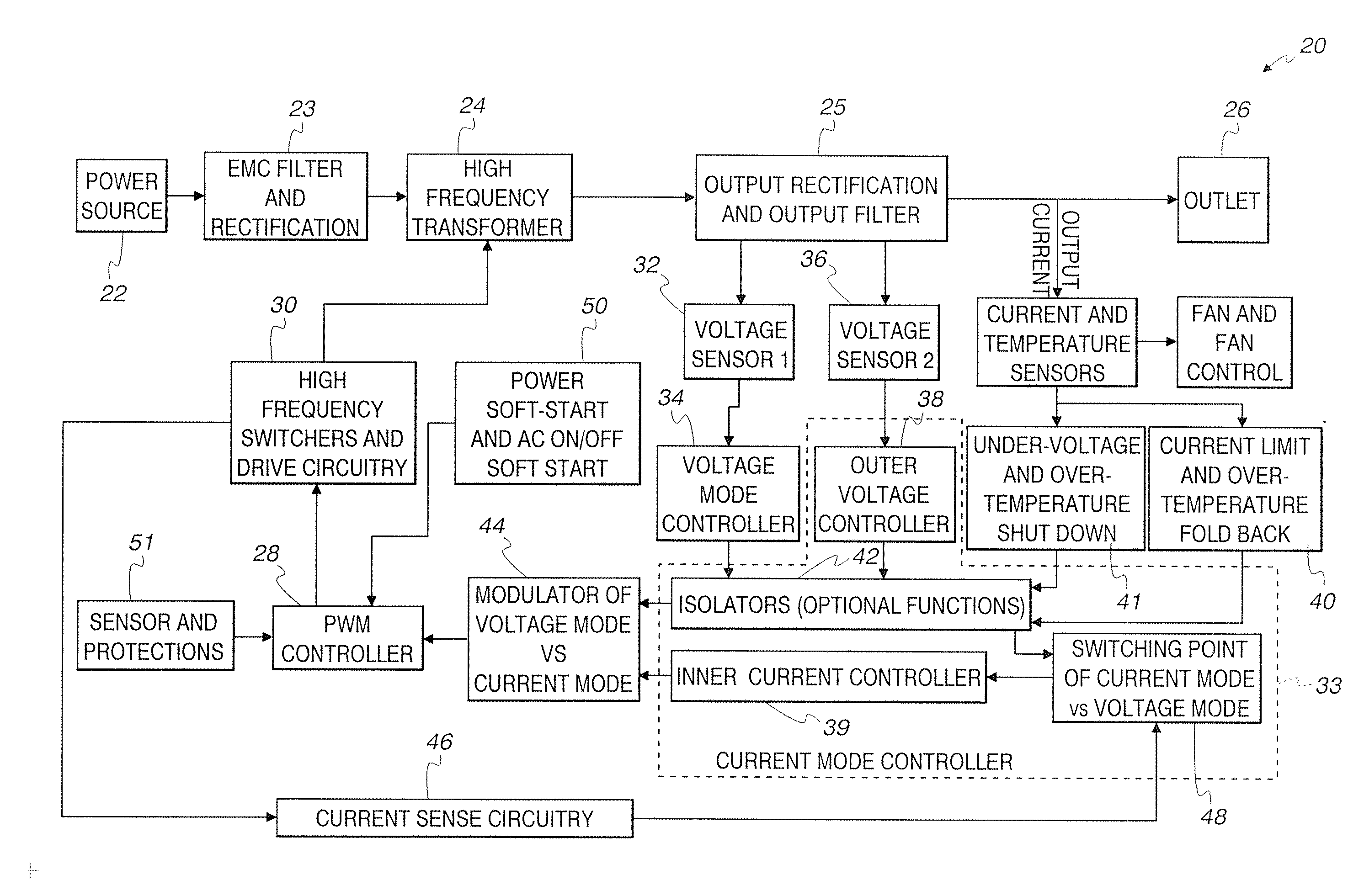
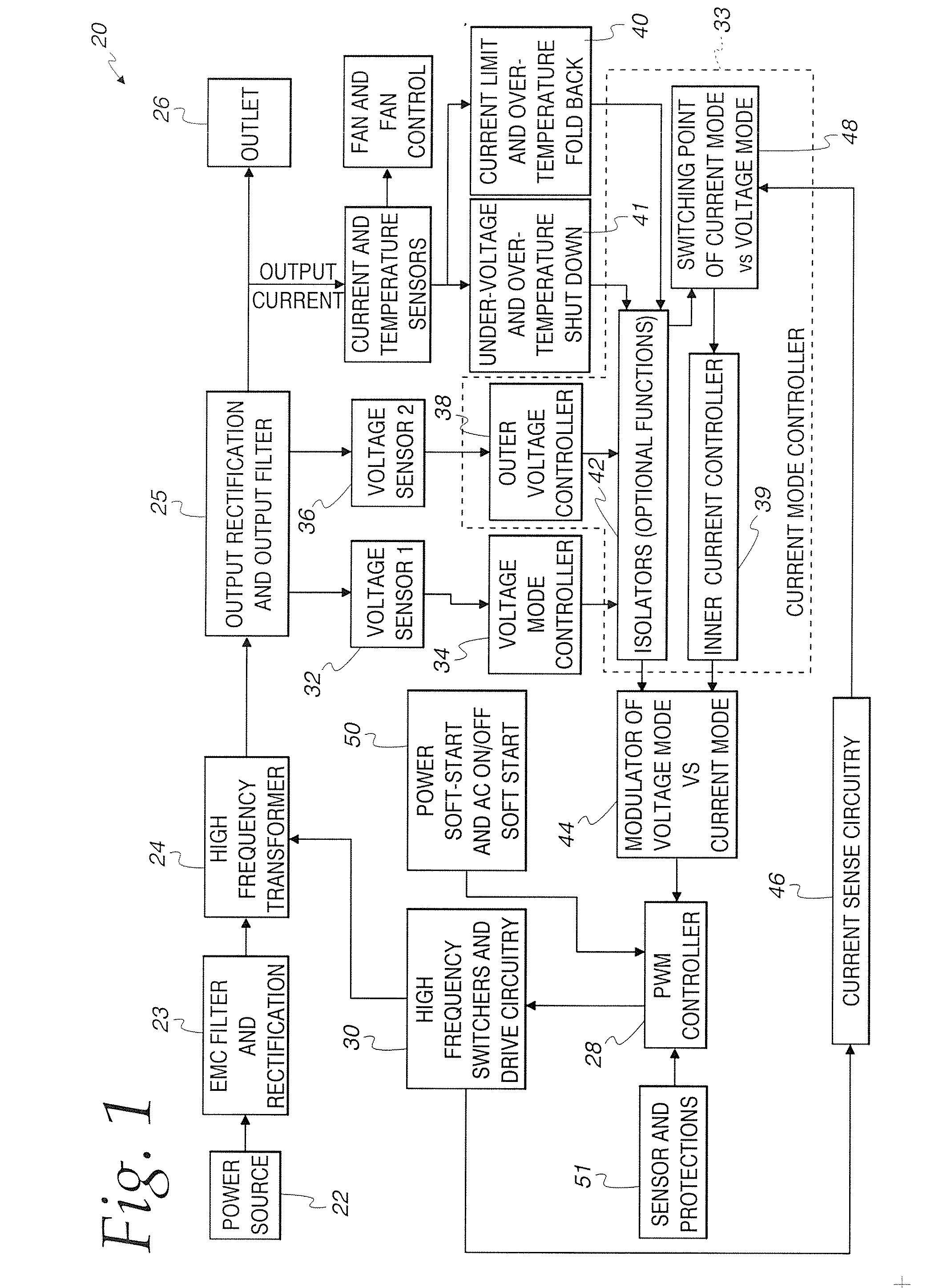
[0028] The present invention relates to a switched mode converter that includes both voltage mode and current mode control. The switched mode converter also includes mode logic for switching between a voltage mode and a current mode to combine the advantages of both current controlled and voltage controlled switched mode converters. The principles of the present invention are applicable to both AC to DC converters as well as DC to DC converters.

Exemplary Block Diagram

[0029] Referring to FIG. 1, the switched mode converter in accordance with the present invention is generally identified with the reference numeral 20. The switched mode converter 20 includes a power source 22, a high frequency transformer 24 and an output terminal 26. AC power sources are rectified by a rectifier 23. EMC filtering is also provided. The output of the high frequency transformer 24 is rectified and further filtered by an output rectification and output filter 25.

[0030] The high frequency transformer 24...


PUM


Abstract

A switched mode converter is disclosed that includes both voltage mode and current mode control. The switched mode converter also includes mode logic for switching between a voltage mode and a current mode. The converter includes current sensing circuitry for sensing the switcher current on the primary side of the transformer and the load current on the secondary side as well as voltage sensing circuitry for sensing the converter output voltage. When the load current is less than a predetermined value, the converter operates in a voltage mode. During the voltage mode, the output voltage of the voltage mode controller is used to control the duty cycle of a pulse width modulation (PWM) controller. When the load current is greater than a predetermined value, the converter operates in a current mode. In a current mode, the primary switcher current is used to control the PWM controller. As such, during a light load in which the converter is voltage controlled, there is no need for a minimum load to stabilize the control loop. In a current-mode, the control loop will have a relatively faster transient response and avoid flux imbalance in push-pull topology. As such, the converter provides the advantages of both known voltage controlled and current controlled switched mode converters. In addition, by the careful arrangement of the locations of a EMC filter, a primary heat sink, a secondary heat sink, a power transformer T1 and other power devices as well as a cooling fan, a smaller EMC filter can be used due to the primary heat sink performing a dual function of thermal management and additionally providing EMC shielding to prevent the noise, for example, the noise generated by the transformer, from reaching the filter. In addition, the primary heat sink is configured to face the air flow while the secondary heat sink is placed close to the fan with its fin direction the same as the direction of the air flow. As such, both the primary and the secondary heat sink get maximum air flow, allowing smaller heat sinks to be used in order to provide a reliable and cost-effective switched mode converter.

Description

CROSS REFERENCE TO RELATED APPLICATIONS [0001] This application claims priority to and the benefit of U.S. provisional patent application No. 60 / 732,169, filed on Nov. 1, 2005.BACKGROUND OF THE INVENTION [0002] 1. Field of the Invention [0003] The present invention relates to a switched mode power supply and more particularly to a switched mode power supply that can be used in AC / DC converters and DC / DC converters which incorporates both voltage mode and current mode logic to provide a multi-mode switched mode power supply which optimizes the transient response time and output regulation relative to known switched mode power supplies. [0004] 2. Description of the Prior Art [0005] Both linear and switched mode power supplies are known in the art. Such power supplies are normally known as converters and are used to provide a regulated source of DC power to a DC device. AC / DC converters are used to convert an unregulated source of AC power to a regulated source of DC power. DC / DC conve...

Claims


Application Information

Patent Timeline
Patent Type & Authority Applications(United States)
IPC IPC(8): G05F1/00
CPCH02M3/33507Y02B70/16H02M2001/0032H02M1/0032Y02B70/10
Inventor CHEN, XIAOPING
Owner SCHUMACHER ELECTRIC CORP
Why Eureka
Try Eureka