Controller and control method for DC-DC converter
a control method and converter technology, applied in the direction of electric variable regulation, process and machine control, instruments, etc., can solve the problems of linear regulator power loss and inability to achieve satisfactory conversion efficiency, and achieve the effect of higher efficiency
- Summary
- Abstract
- Description
- Claims
- Application Information
AI Technical Summary
Benefits of technology
Problems solved by technology
Method used
Image
Examples
first embodiment
[0032] A DC-DC converter 12 according to the present invention will now be described with reference to the drawings.
[0033]FIG. 10 is a schematic block diagram of an electronics device 10 including the DC-DC converter 12. The electronics device 10 is portable, and is driven using power supplied from its built-in battery 11. The battery 11 is connected to the DC-DC converter 12 as a power supply circuit. The DC-DC converter 12 is connected to an internal circuit 13, such as a CPU. The DC-DC converter 12 converts an input voltage Vin supplied from the battery 11 to an output voltage Vout, which is a constant voltage for operating the internal circuit 13. The DC-DC converter 12 supplies the output voltage Vout to the internal circuit 13.
[0034] The configuration of the DC-DC converter 12 will now be described.
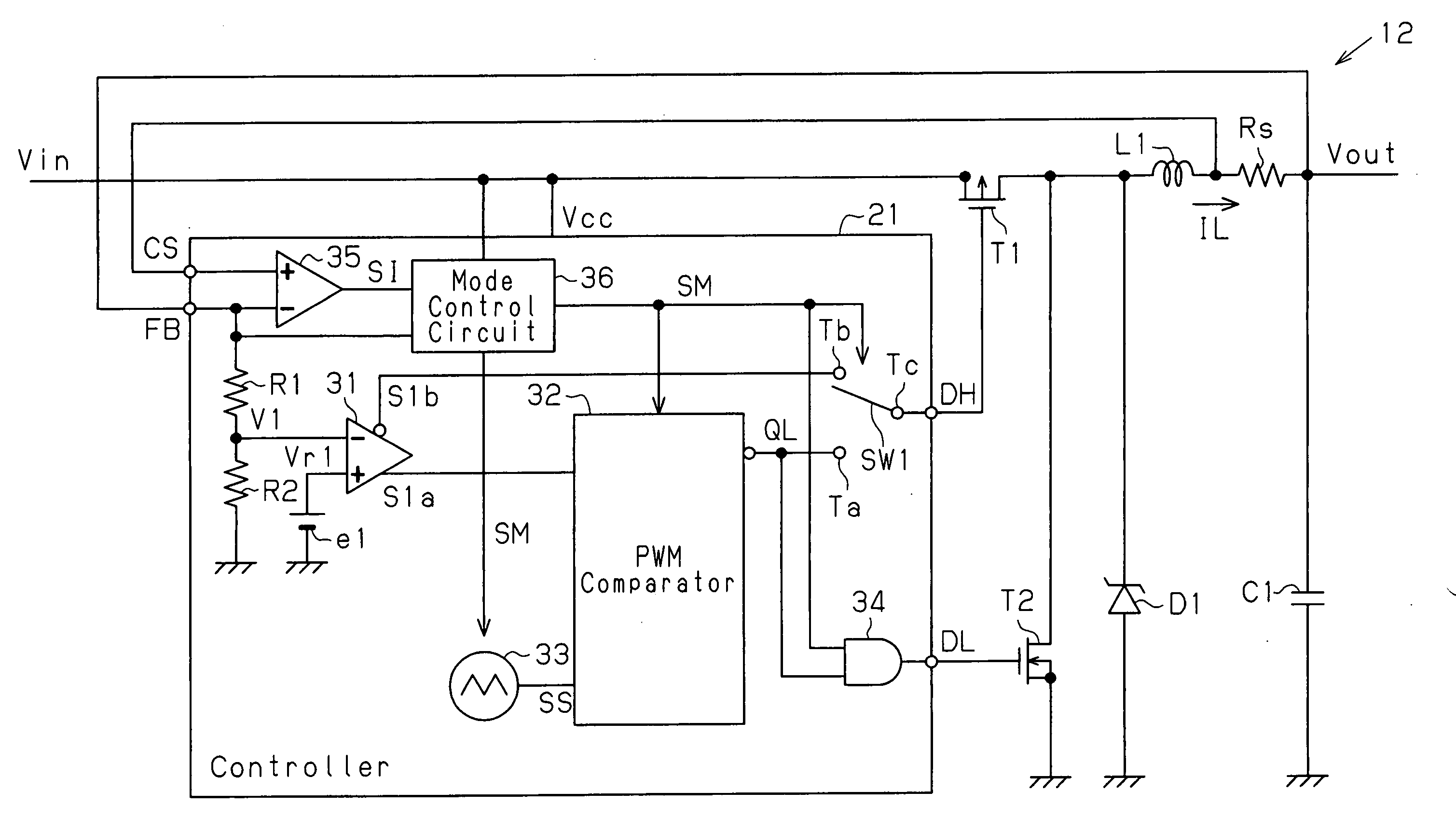
[0035] Referring to FIG. 7, the DC-DC converter 12, which is a voltage control mode DC-DC converter, includes a controller 21, a first output transistor T1, a second output transi...
second embodiment
[0120] A DC-DC converter 70 according to the present invention will now be described with reference to the drawing.
[0121]FIG. 13 is a schematic block diagram of the DC-DC converter 70 in the second embodiment. The DC-DC converter 70, which is a current control mode DC-DC converter, includes a controller 71, output transistors T1 and T2, a choke coil L1, a smoothing capacitor C1, a diode D1, and a current detection resistor Rs. Output voltage Vout is output via the current detection resistor Rs.
[0122] In the controller 71, a voltage amplifier 35 has a non-inverting input terminal provided with a feedback signal CS and an inverting input terminal provided with a feedback signal FB. The voltage amplifier 35 amplifies the voltage produced between the two terminals of the current detection resistor Rs based on the output current flowing through the current detection resistor Rs to provide a mode control circuit 36 and a comparator 73 with an amplified signal SI. An error amplifier 31 of...
PUM
 Abstract
Description
Claims
Application Information
 - R&D
- Intellectual Property
- Life Sciences
- Materials
- Tech Scout
- Unparalleled Data Quality
- Higher Quality Content
- 60% Fewer Hallucinations
Browse by: Latest US Patents, China's latest patents, Technical Efficacy Thesaurus, Application Domain, Technology Topic, Popular Technical Reports.
© 2025 PatSnap. All rights reserved.Legal|Privacy policy|Modern Slavery Act Transparency Statement|Sitemap|About US| Contact US: help@patsnap.com


