Temperature compensation system for a coordinate measuring machine

a technology of temperature compensation and coordinate measuring machine, which is applied in the direction of mechanical measuring arrangement, instruments, manufacturing tools, etc., can solve the problems of reducing errors, limited accuracy of coordinate measuring machine, and increasing the cost of reducing errors

Active Publication Date: 2004-12-14
HEXAGON TECH CENT GMBH
View PDF30 Cites 44 Cited by
  • Summary
  • Abstract
  • Description
  • Claims
  • Application Information

AI Technical Summary

Benefits of technology

In another aspect, a coordinate measuring machine includes an elongated beam movable in one direction generally perpendicular to its direction of elongation, at least one rail that is disposed on the beam and extends in a direction generally parallel to the direction of elongation of the beam, the rail being formed of a material having a coefficient of thermal expansion different from that of the beam, a carriage that is movable along the rail in the direction of elongation of the beam, and a bar that is disposed on the beam generally on an opposite side of a center of mass of the beam from the rail, the bar having a coefficient of thermal expansion, a cross-sectional dimension, a stiffness and a spacing from the center of mass of the beam such that the bar substantially balances any thermal stresses on the beam produced by differential expansion or contraction of the beam and the rail with changes in temperature.
In yet another aspect of the invention, a coordinate measuring machine is disclosed which includes a carriage movable along a beam in a first direction, a ram movable with respect to the carriage in a second direction generally orthogonal to the first direction, the ram having a rail extending in the second direction disposed on one side of the ram and along which the ram travels with respect to the carriage, the rail having a coefficient of th...

Problems solved by technology

The accuracy of a coordinate measuring machine is limited by geometric errors, such as inaccuracies in the scales or other measuring devices, and faults in the guideways or other elements which define machine motion.
These inaccuracies can cause measurement errors when the machine is operated at a reference temperature, which is usually 20.degree. C.
However, reduction of errors becomes progressively more expensive as required accuracies increase.
This approach is impractical because of a huge amount of data which must be stored for large machines and because of the time required to measure such data.
In reality, however, there are scale errors and the guideways are not completely straight or perfectly free from twists.
In addition to the above mentioned so-called geometric errors, the accuracy of a coordinate measuring machine is in general also affected by thermally induc...

Method used


Image

  • Temperature compensation system for a coordinate measuring machine
  • Temperature compensation system for a coordinate measuring machine
  • Temperature compensation system for a coordinate measuring machine

Examples


Embodiment Construction

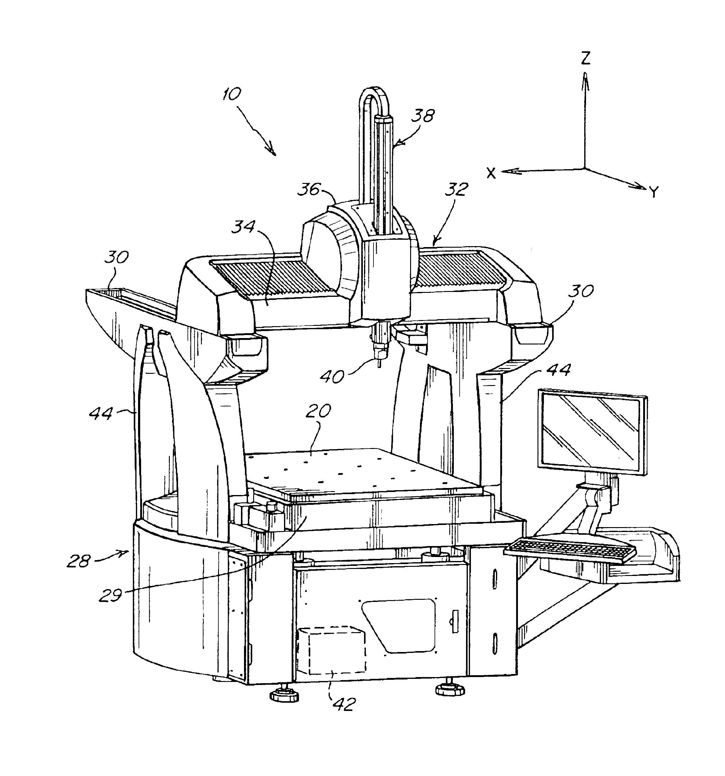
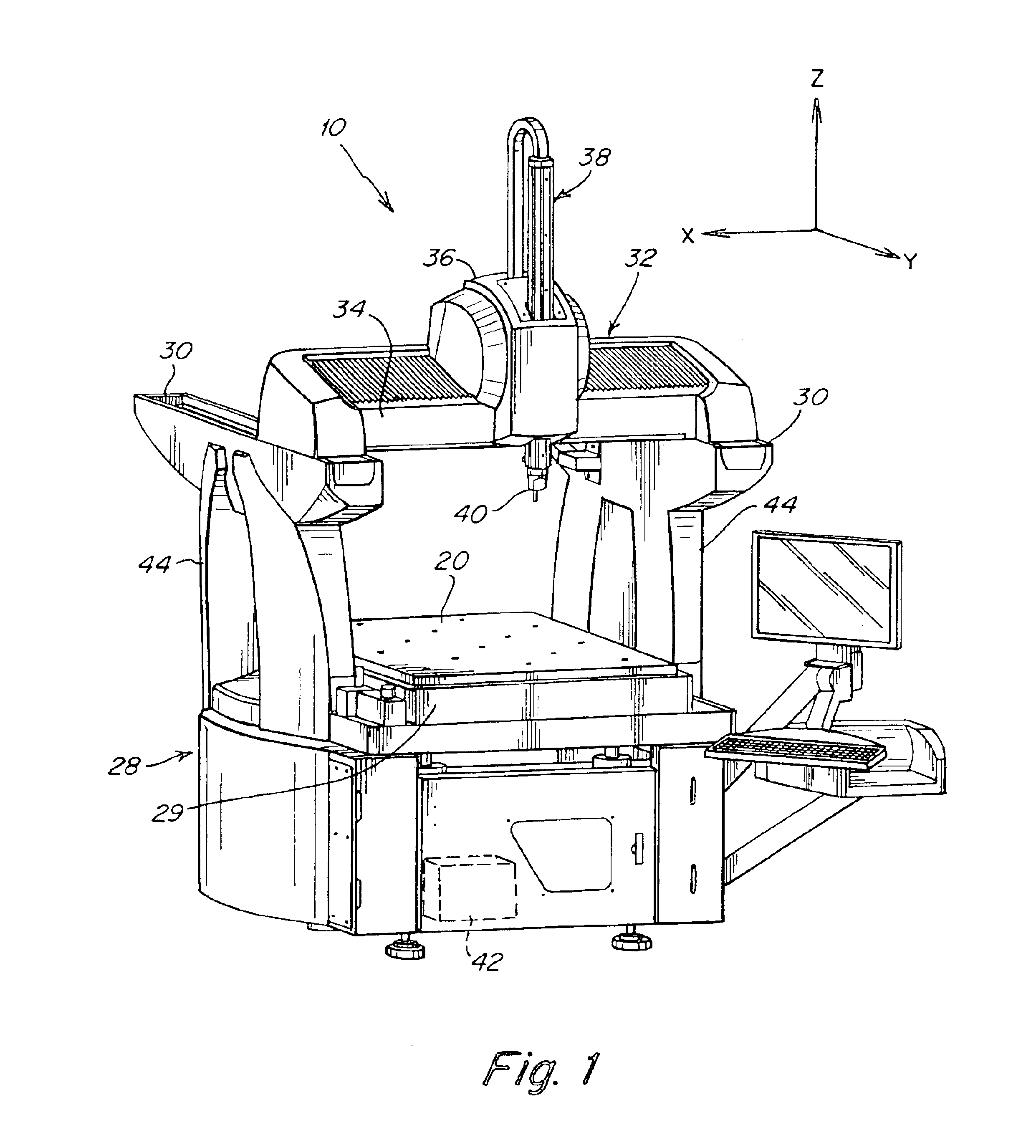
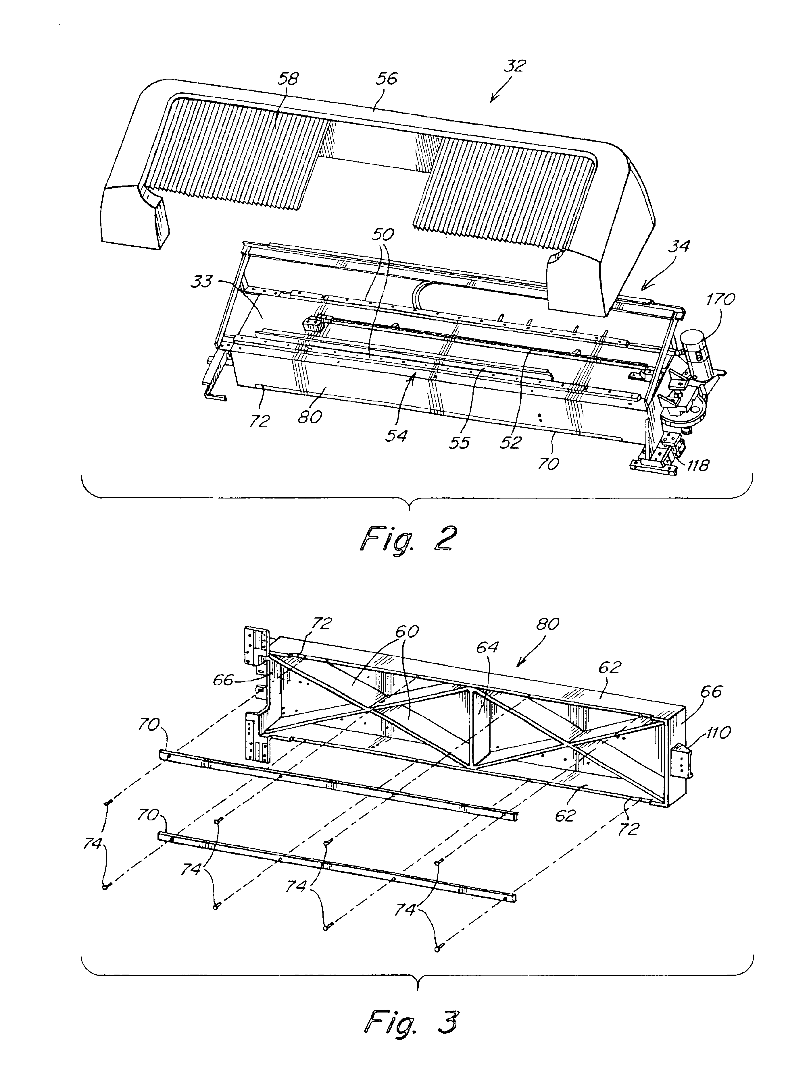
This invention relates to machines having an element, such as a carriage, that moves along guideways, such as rails. This invention is directed to minimizing thermal errors in such machines by applying design techniques that make the machine or components of the machine more or less insensitive to changes in the thermal environment. This invention does not deal with geometric errors at reference temperature. Thus, the machines must still be calibrated at the reference temperature. However, this invention eliminates or minimizes the need for complex thermal error compensation.

The various aspects of this invention offset or accommodate differential expansion and contraction of one portion of the machine with respect to another portion with changes in temperature. In one aspect, the guideways or rails on which the element rides rest on a beam or support which has a coefficient of thermal expansion different from that of the rails. Members, such as bars, are employed to balance the ther...


PUM


Abstract

A machine, such as a coordinate measuring machine, having an element and a structure movable with respect to each other along rails, wherein the rails have a different coefficient of thermal expansion than the structure to which they are attached. In one embodiment, a bar is disposed on the structure opposite the rails. This bar has a coefficient of thermal expansion, a stiffness, a spacing from the neutral axis of the structure, and a cross-sectional dimension such that the bar balances any thermal stresses in the structure caused by differential expansion or contraction of the structure and the rails with temperature changes to minimize any bending of the structure. In one embodiment, two rails are disposed on a beam, and a carriage travels on the two rails. For each rail, there is an associated bar disposed on an opposite surface of the beam. In another aspect, a pin extends into an elongated slot on a slide associated with the structure to allow the structure to expand and contact. In yet another aspect, a movable element, such as a carriage, is coupled to an associated slide riding along the rails by a leaf spring to accommodate expansion and contraction of the element.

Description

This invention relates generally to machines having an element movable along guideways, such as a coordinate measuring machine, and more particularly to coordinate measuring machines that can accommodate materials having different coefficients of thermal expansion while maintaining a high level of accuracy and stability at different temperatures.Coordinate measuring machines are used for dimensional inspection of workpieces, such as machined or molded parts. A workpiece typically is secured to a fixed table and a measuring probe is secured to a ram which is movable in three dimensions. To measure the position of a point on the workpiece, the probe is brought into contact with the point, and measuring scales or other sensors on the machine are read. The position of the point is typically expressed in X, Y and Z coordinates within a working volume of the machine. To measure a distance between two points, the points are contacted successively, the coordinates of both points are read, a...

Claims


Application Information

Patent Timeline
IPC IPC(8): G01B5/00G01B5/008
CPCG01B5/0014B23Q11/0003G01B5/008
Inventor WEEKERS, WILHELMUS GODEFRIDUSHUPKAU, JENSPAYETTE, DAVID W.
Owner HEXAGON TECH CENT GMBH
Why Eureka
Try Eureka