Optimization of milking

a technology of optimizing and milking, applied in the direction of milking devices, dairy products, catheters, etc., can solve the problems of affecting the optimal use of udder quarters, heavy expenditure of automatic milking machines, limited milk production capacity,

Inactive Publication Date: 2004-12-14
DELAVAL HLDG AB
View PDF16 Cites 27 Cited by
  • Summary
  • Abstract
  • Description
  • Claims
  • Application Information

AI Technical Summary

Benefits of technology

It is yet a further object to provide such method, which is simple, reliable, of low cost, and easy to-implement.
It is still a further object to provide such method, which is very flexible and takes into account different milking start times for different udder quarters of a cow and different milk content in different udder quarters.
By the provision of a flexible threshold value adjustment for the udder quarters(s), still being milked after the first udder quarter is finished (i.e. when the milk flow therefrom has reached the threshold value for that udder quarter) the threshold value(s) for this (theses) remaining udder quarter(s) can be raised in order to decrease the total milking time of the animal, while some amount of milk, which would conventionally be drawn, is left in the last finished udder quarter, or optionally udder quarters. However, as the milking capacity of the milking facility is now more rapidly freed to be used for the milking of another unmilked animal, the overall milk production by the milking facility can be increased.

Problems solved by technology

An automatic milking machine involves heavy expenditure and has a limited milk production capacity.
How to operate and use such a milking machine, which animals are visiting on a voluntary basis, in order to obtain an overall dairy farm performance is an arduous task.
While such approach provides for an increased milk yield and an improved overall milking method, it is impaired by certain limitations.
Further, the udder quarters of a cow, for instance, are separate and individual milk producing units and thus the use of one specific value for all udder quarters may not be optimal.

Method used


Image

  • Optimization of milking
  • Optimization of milking

Examples


Embodiment Construction

In the following description, for purposes of explanation and not limitation, specific details are set forth, such as particular techniques and applications in order to provide a thorough understanding of the present invention. However, it will be apparent to one skilled in the art that the present invention may be practised in other embodiments that depart from these specific details. In other instances, detailed descriptions of well-known techniques are omitted so as not to obscure the description of the present invention with unnecessary details.

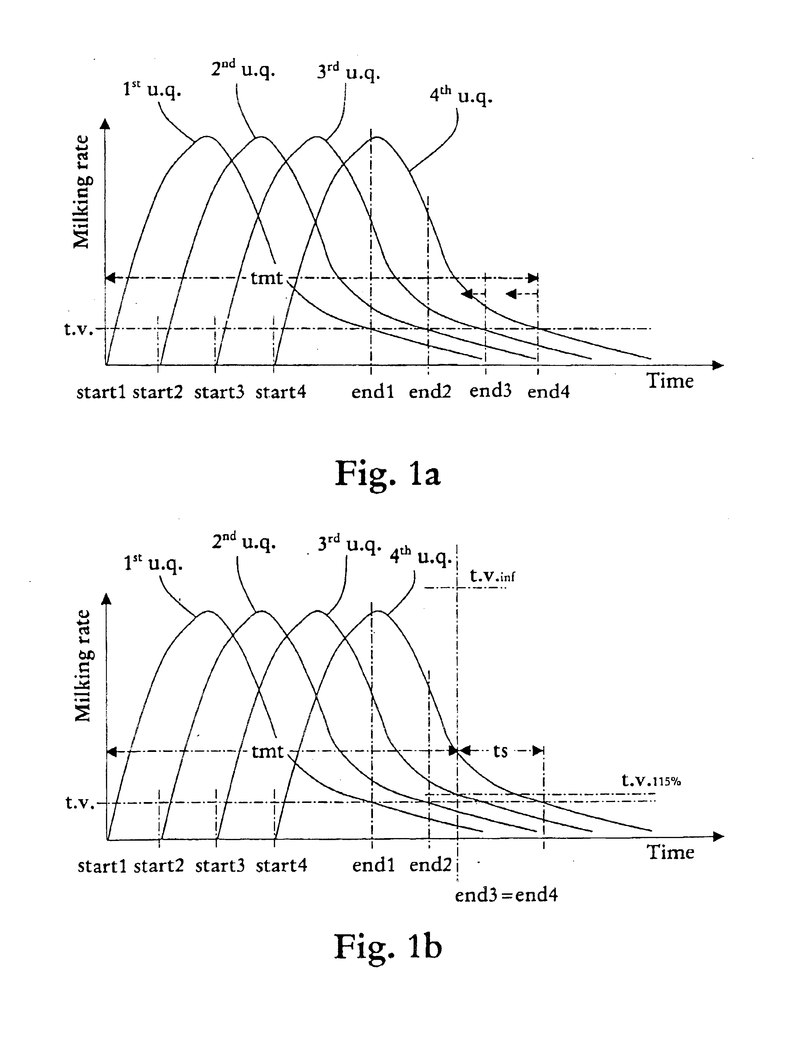
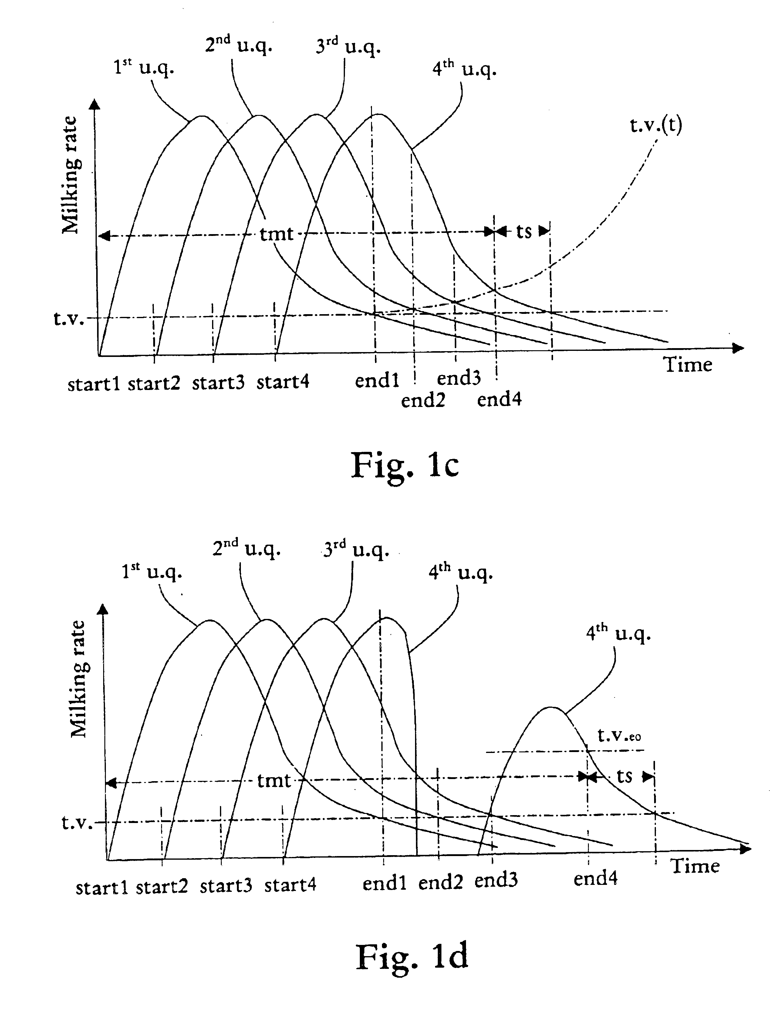
The present invention is advantageously implemented in an automatic milking facility arranged for voluntary milking of freely walking cows, i.e. the cows enter the milking facility in order to be milked when they need to (or want to). The milking facility includes four teatcups, each being individually connectable to a source of vacuum, and each being connected to an end unit for collection of milk. Further, the milking facility is provid...


PUM


Abstract

A more effective method of automatically milking animals in an automatic milking facility is disclosed. The method includes (i) assigning a respective threshold value (t.v.) to each of the udder quarters (1<st >u.q.; 2<nd >u.q.; 3<rd >u.q.; 4u.q.) of an animal to be milked indicating when the milking of the corresponding udder quarter is to be ended; (ii) measuring the milk flow from each udder quarter of animal during milking; and (iv) ending the milking of an udder quarter of the animal (end1; end2; end3; end4) in dependence on the measured milk flow from that udder quarter reaches the corresponding threshold value. The threshold value of the udder quarter (4u.q.) of the animal, for which the ending of milking very last remains is raised (t.v.115%; t..V.inf; t.v.(t); t.v.eo) subsequently to the very first ending of milking of an udder quarter of the animal, to thereby shorten the total milking time (tmt) of the animal, and thus more rapidly free milking capacity of the milking facility to be used for the milking of a further animal.

Description

The present invention generally relates to dairy farming and to milking of dairy animals therein.Particularly, the invention relates to an improved method of automatically milking animals, to an automatic milking facility adapted to perform said method, and to a computer program product for controlling the milking performed by a computer-controlled milking facility in accordance with above said method when run on the computer of said computer-controlled milking facility.DESCRIPTION OF RELATED ART AND BACKGROUND OF THE INVENTIONIn modern dairy farm industry there are continuous research and development activities in order to improve the efficiency of various activities such as machine milking, which, inter alia, involves increased milk yield and reduced milking time.A major trend in this respect is an increased degree of automation of the various activities. For instance, machine milking may be performed by milking robots in a completely automated manner. Such an automatic milking sy...

Claims


Application Information

Patent Timeline
Patent Type & Authority Patents(United States)
IPC IPC(8): A01J5/01A01J5/007
CPCA01J5/01A01J5/007
Inventor SJOLUND, MARTINHANSSON, HANS
Owner DELAVAL HLDG AB
Why Eureka
Try Eureka