Multi-clutch arrangement
a multi-clutch, clutch technology, applied in the direction of mechanical actuated clutches, friction linings, couplings, etc., can solve the problems of occupying a large amount of space, and affecting the operation of the clutch
- Summary
- Abstract
- Description
- Claims
- Application Information
AI Technical Summary
Benefits of technology
Problems solved by technology
Method used
Image
Examples
Embodiment Construction
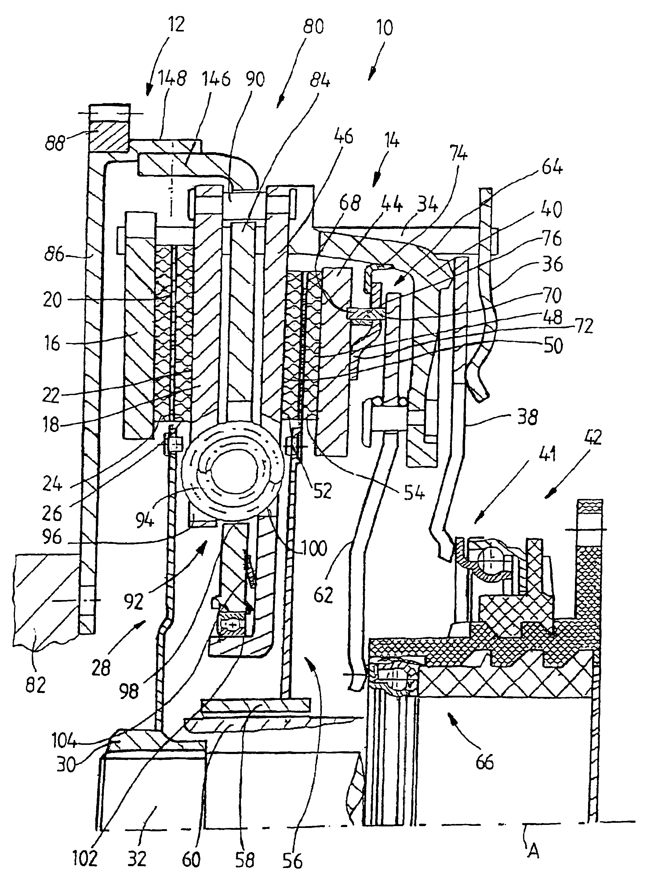
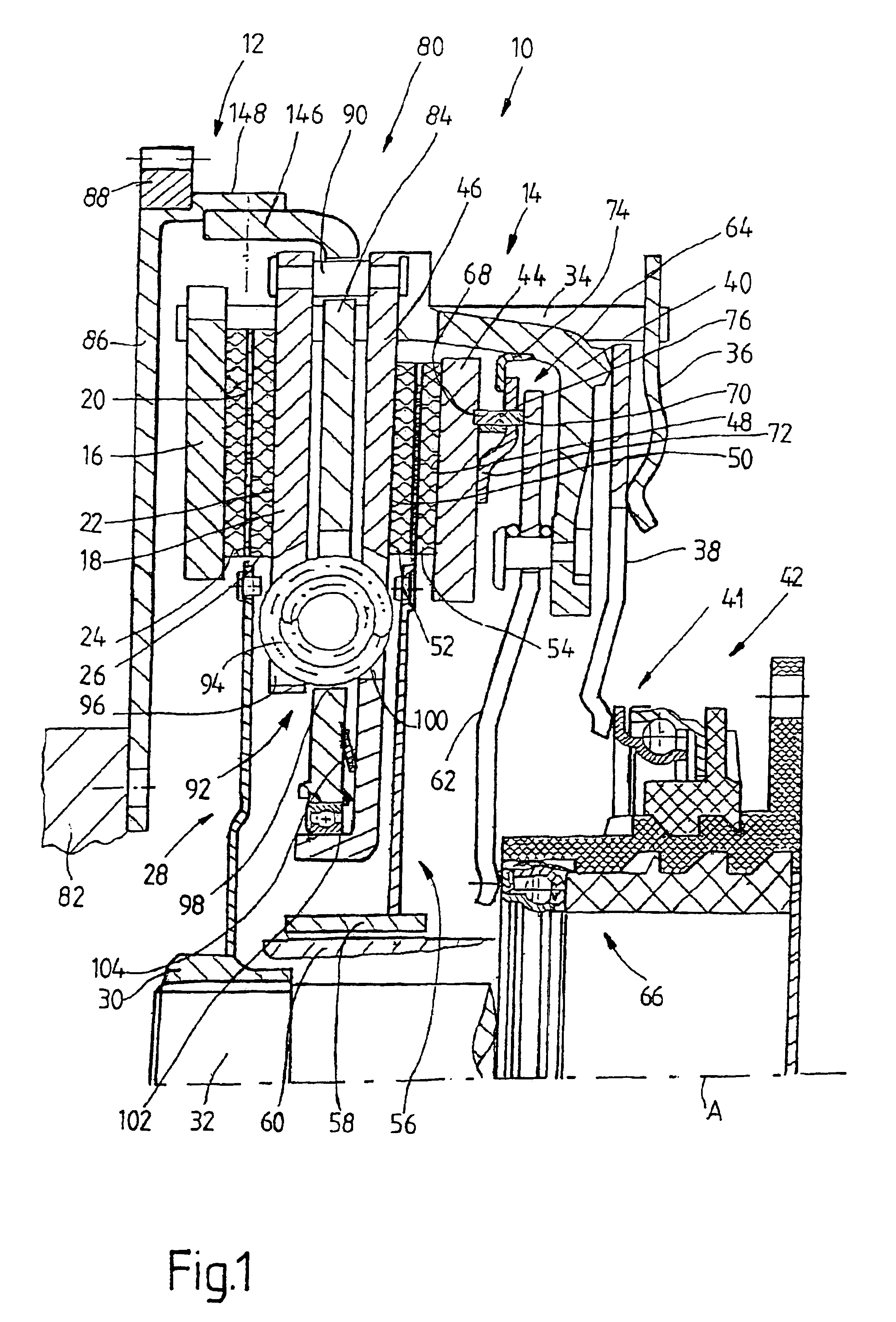
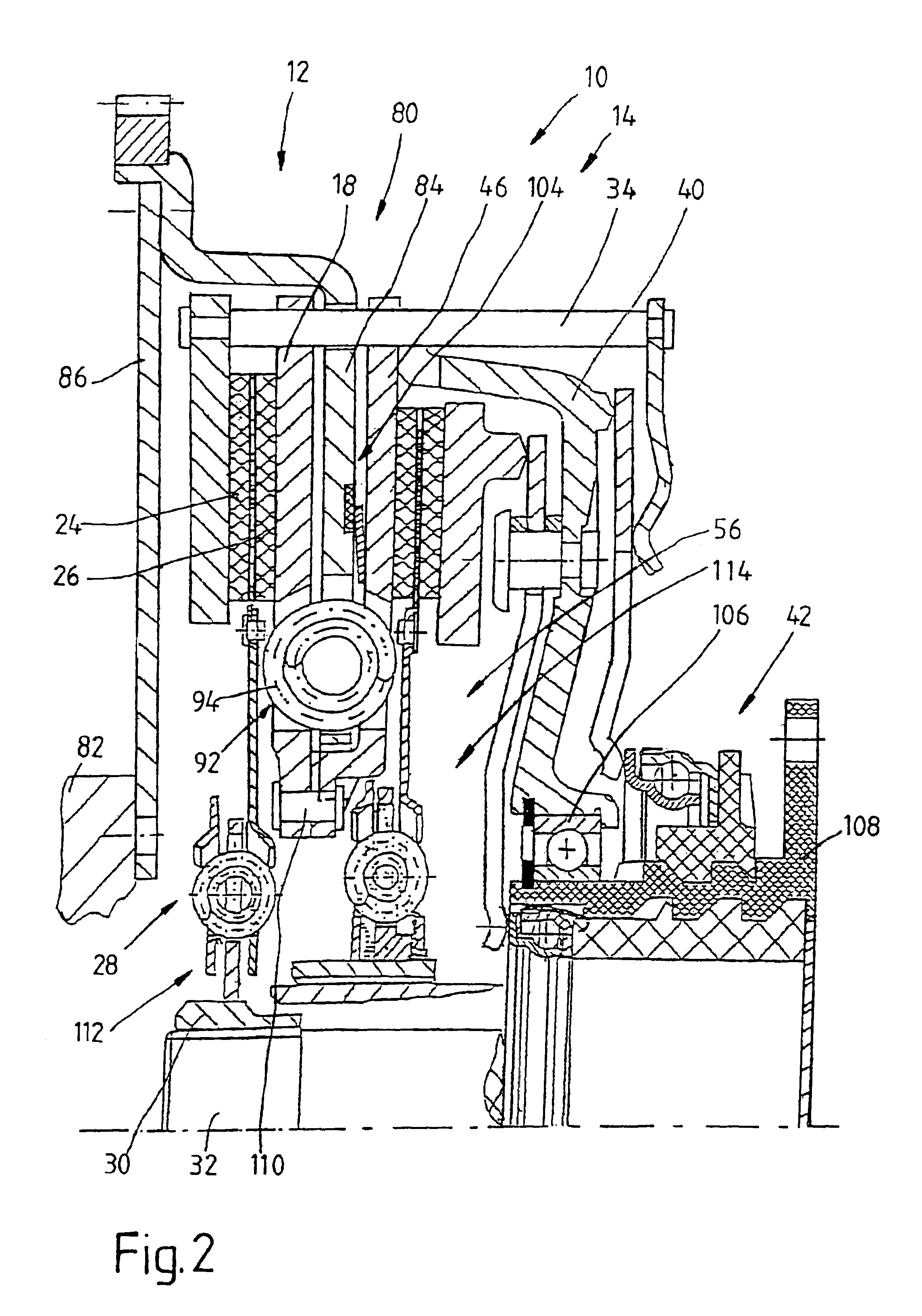
FIG. 1 shows a dual clutch 10 according to the invention, which comprises two clutch areas 12, 14, which follow each other in the direction of an axis of rotation A. The first clutch area 12 comprises a pressure plate 16 and an opposing support plate 18, which face each other in the direction of the axis of rotation A. Between these two plates 16, 18, i.e., between the frictional surfaces 20, 22 of these plates, lie the friction linings 24, 26 of a clutch disk 28 of the first clutch area 12. Radially on the inside, the clutch disk 28 is provided with a hub area 30 for the nonrotatable connection to a first transmission input shaft 32.
Whereas the opposing support plate 18, as will be described below, is connected to the pressure plate 16 with essentially no freedom of rotation and is also essentially stationary in the direction of the axis of rotation A--relative to the overall arrangement of the dual clutch--, the pressure plate 16 can be pushed back and forth in the axial direction...
PUM
 Abstract
Description
Claims
Application Information
 - R&D
- Intellectual Property
- Life Sciences
- Materials
- Tech Scout
- Unparalleled Data Quality
- Higher Quality Content
- 60% Fewer Hallucinations
Browse by: Latest US Patents, China's latest patents, Technical Efficacy Thesaurus, Application Domain, Technology Topic, Popular Technical Reports.
© 2025 PatSnap. All rights reserved.Legal|Privacy policy|Modern Slavery Act Transparency Statement|Sitemap|About US| Contact US: help@patsnap.com


