Multi-clutch arrangement

a multi-clutch, clutch technology, applied in the direction of mechanical actuated clutches, friction linings, couplings, etc., can solve the problems of occupying a large amount of space, and affecting the operation of the clutch

Inactive Publication Date: 2003-05-01
ZF SACHS AG
View PDF7 Cites 61 Cited by
  • Summary
  • Abstract
  • Description
  • Claims
  • Application Information

AI Technical Summary

Problems solved by technology

Very strong torque-induced vibrations are excited in various speed ranges in these types of drive systems, such as direct-injection diesel engines, and unless these vibrations are damped, they are transmitted to the following part of the drive train and lead not only to considerable stress on the various comp

Method used


Image

  • Multi-clutch arrangement
  • Multi-clutch arrangement
  • Multi-clutch arrangement

Examples


Embodiment Construction

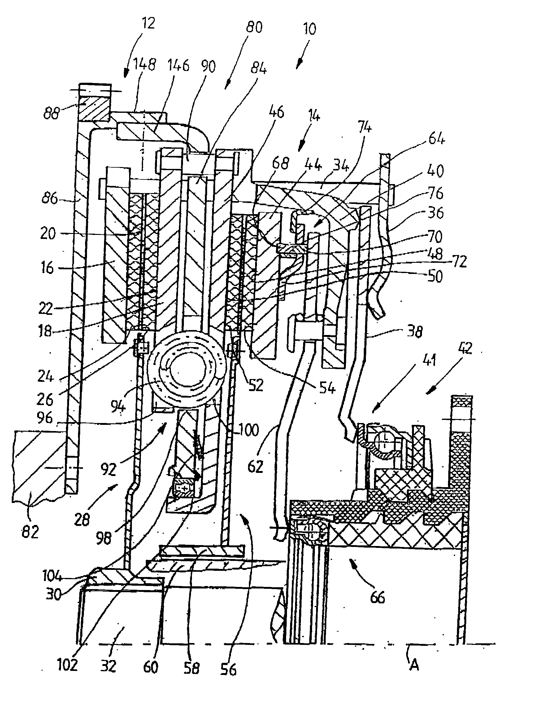
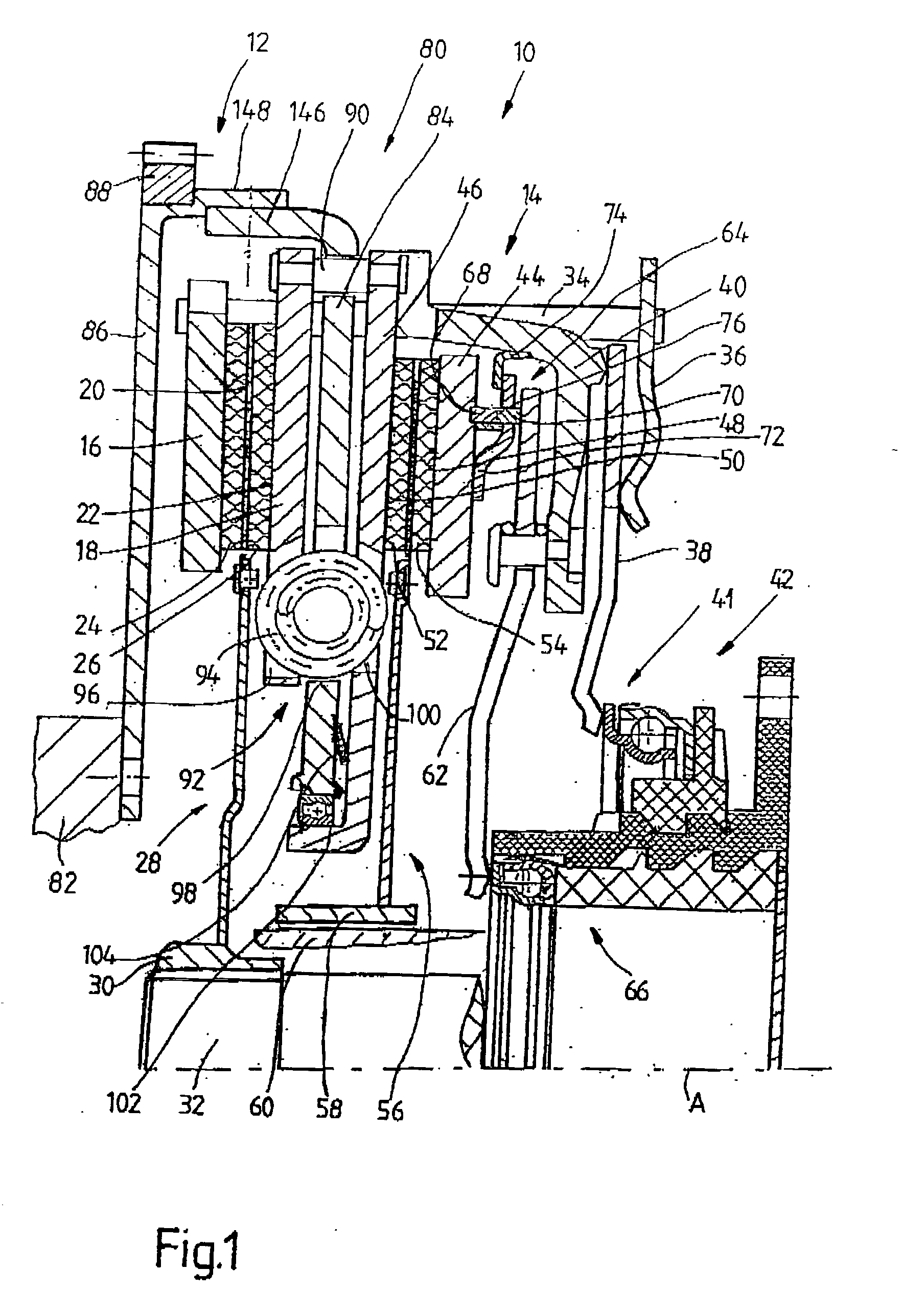
[0030] FIG. 1 shows a dual clutch 10 according to the invention, which comprises two clutch areas 12, 14, which follow each other in the direction of an axis of rotation A. The first clutch area 12 comprises a pressure plate 16 and an opposing support plate 18, which face each other in the direction of the axis of rotation A. Between these two plates 16, 18, i.e., between the frictional surfaces 20, 22 of these plates, lie the friction linings 24, 26 of a clutch disk 28 of the first clutch area 12. Radially on the inside, the clutch disk 28 is provided with a hub area 30 for the nonrotatable connection to a first transmission input shaft 32.

[0031] Whereas the opposing support plate 18, as will be described below, is connected to the pressure plate 16 with essentially no freedom of rotation and is also essentially stationary in the direction of the axis of rotation A--relative to the overall arrangement of the dual clutch--the pressure plate 16 can be pushed back and forth in the axi...


PUM


Abstract

A multi-clutch arrangement, especially a dual clutch for motor vehicles, comprising a first clutch area with a first pressure plate arrangement, with a first opposing support arrangement, and with a first clutch disk arrangement , which can be clamped between the first pressure plate arrangement and the first opposing support arrangement to transmit torque via the first clutch area; and a second clutch area with a second pressure plate arrangement, with a second opposing support arrangement, and with a second clutch disk arrangement, which can be clamped between the second pressure plate arrangement and the second opposing support arrangement to transmit torque via the second clutch area. A torsional vibration damper arrangement is assigned to at least one of the clutch areas, and where-relative to an axis of rotation (A)-the torsional vibration damper arrangement is arranged at least partially in the axial area of the first clutch area and/or of the second clutch area.

Description

[0001] 1. Field of the Invention[0002] The present invention pertains to a multi-clutch arrangement, especially a dual clutch for motor vehicles, comprising a first clutch area with a first pressure plate arrangement, with a first opposing support arrangement, and with a first clutch disk arrangement, which can be clamped between the first pressure plate arrangement and the first opposing support arrangement to transmit torque via the first clutch area; and a second clutch area with a second pressure plate arrangement, with a second opposing support arrangement, and with a second clutch disk arrangement, which can be clamped between the second pressure plate arrangement and the second opposing support arrangement to transmit torque via the second clutch area.[0003] 2. Description of the Related Art[0004] A multi-clutch arrangement of this type, designed as a dual clutch, is known from EP 0 185 176 A1. In this clutch, the two clutch areas are arranged in sequence in the direction of ...

Claims


Application Information

Patent Timeline
IPC IPC(8): F16D21/06F16F15/123
CPCF16D21/06F16D2021/0607F16D2021/0615F16F15/123F16D2021/0684F16D2300/14F16D2021/0623
Inventor CARLSON, CORAWETH, JURGENKISTER, IGORPEINEMANN, BERNDFELDHAUS, REINHARDBACH, HARTMUT
Owner ZF SACHS AG
Why Eureka
Try Eureka