Vibration damper with adjustable damping force

a damping force and vibration damper technology, applied in the direction of vibration dampers, shock absorbers, springs/dampers, etc., can solve the problems of image evaluation, high computer-intensive process, and not always reliabl

Inactive Publication Date: 2006-05-25
ZF FRIEDRICHSHAFEN AG
View PDF10 Cites 9 Cited by
  • Summary
  • Abstract
  • Description
  • Claims
  • Application Information

AI Technical Summary

Benefits of technology

[0009] The great advantage is that the delay time of the adjustable damping valve, which can be overcome only with considerable technical effort, can be compensated by a simple additional damping valve. That is, this additional damping valve brakes the peak velocities which the piston rod reaches when, for example, the vehicle travels over an obstacle. Especially when the piston rod reaches its point of maximum inward travel at very high velocity, damage can occur to the body of the vehicle, which in turn can be prevented only by reinforcing the body. When such a damping force-increasing auxiliary damping valve is present, it is possible to slow down the system, that is, to increase the time it takes for the actuators to be reset after the signal has been picked up by the sensors. This has the effect of lowering costs and can make it possible to lower the minimal damping force of the vibration damper even more, which provides an advantageous increase in driving comfort. When an obstacle is actually encountered on the road, however, the additional damping valve provides the necessary safety.

Problems solved by technology

Image evaluation, however, is a highly computer-intensive process, and it is not always reliable.
This approach, however, will inevitably exceed certain cost limits and make it impossible to market the product.
It would also be possible to use tension or compression stops, but these are always dependent on distance and for this reason lead to a loss of comfort when, for example, the elastic deflections are slow during straight-ahead travel of the vehicle.

Method used


Image

  • Vibration damper with adjustable damping force
  • Vibration damper with adjustable damping force
  • Vibration damper with adjustable damping force

Examples


Embodiment Construction

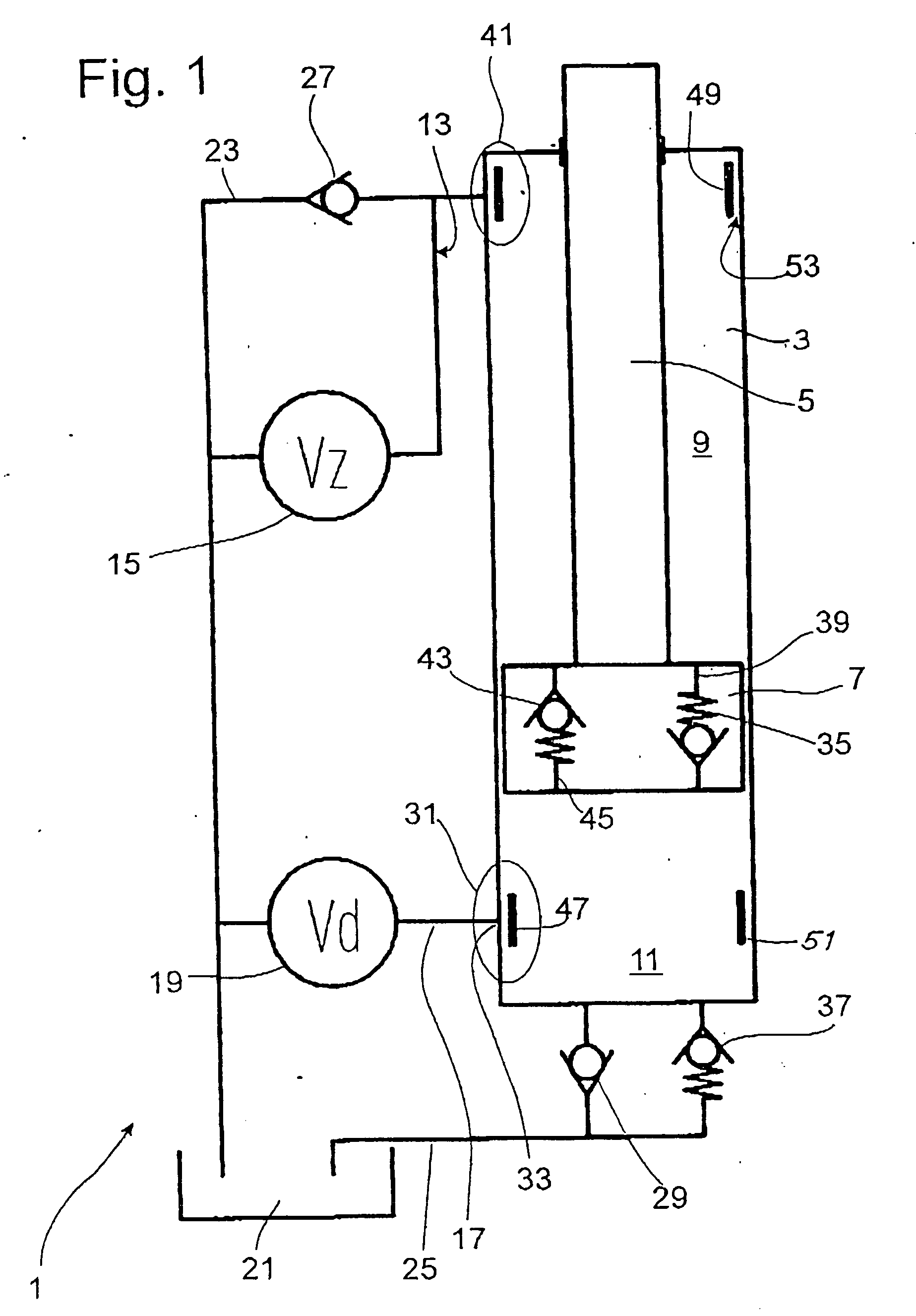
[0029]FIG. 1 shows a diagram of a vibration damper 1, which comprises a damping medium-filled cylinder 3, in which a piston rod 5, together with a piston 7, is guided with freedom of axial movement. The piston 7 divides the cylinder 3 into a working space 9 on the piston rod side and a working space 11 on the side opposite the piston rod. In principle, the piston can be a simple displacement body without through-channels. The piston rod-side working space 9 is connected to an adjustable damping valve 15 by a fluid connection 13. The working space 11 on the side opposite the piston rod also has a fluid connection 17, which leads to an independently adjustable damping valve 19. The damping medium displaced from the working spaces in question and thus to the adjustable damping valves then flows to a compensating space 21. The piston rod-side working space 9 and the space 11 on the opposite side are connected to the compensating space 21 by return lines 23, 25 in combination with nonret...


PUM


Abstract

A vibration damper with adjustable damping force includes a cylinder containing a damping medium, a piston rod which is axially movable in the cylinder, and a piston arranged for axial movement in the damping medium, the piston being connected to the piston rod and dividing the cylinder into a working space around the piston rod and a working space opposite the piston rod. At least one adjustable damping valve is connected to a respective at least one of the working spaces by a fluid connection through which damping medium can flow with a flow velocity, and an auxiliary damping valve is connected in series with each adjustable damping valve with respect to the flow, the auxiliary damping valve moving in a closing direction as a function of the flow velocity.

Description

BACKGROUND OF THE INVENTION [0001] 1. Field of the Invention [0002] The invention pertains to a vibration damper with adjustable damping force, including a cylinder containing a damping medium, a piston rod which is axially movable in the cylinder, a piston arranged for axial movement in said damping medium, the piston being connected to the piston rod and dividing the cylinder into a working space around the piston rod and a working space opposite the piston rod, and an adjustable damping valve connected to one of the working spaces by a fluid connection through which damping medium can flow with a flow velocity. [0003] 2. Description of the Related Art [0004] Adjustable vibration dampers such as those known from U.S. Pat. No. 5,937,975 are intended to solve the conflict between a somewhat harder damping force setting, which tends to offer more driving safety, and a softer damping force setting, which provides greater comfort. The variables which represent the movement of the vehic...

Claims


Application Information

Patent Timeline
Patent Type & Authority Applications(United States)
IPC IPC(8): F16F9/00
CPCF16F9/34F16F9/46F16F9/512
Inventor FORSTER, ANDREAS
Owner ZF FRIEDRICHSHAFEN AG
Why Eureka
Try Eureka