Method and system for assigning and binding a network address of a ballast

a network address and ballast technology, applied in the direction of electric controllers, ignition automatic control, instruments, etc., can solve the problems of reducing or focusing the transmission range, and limiting the convenience and use of binding each receiver

Inactive Publication Date: 2004-12-14
SIGNIFY HLDG BV
View PDF6 Cites 203 Cited by
  • Summary
  • Abstract
  • Description
  • Claims
  • Application Information

AI Technical Summary

Problems solved by technology

However, under such circumstances, decorative and operational choices of a user become limited to deciding among systems as opposed to deciding among individual fixtures or lamps from various systems.
Such a reduction or focusing of the transmission range however limits the convenience and use of binding each receiver to the remote control.

Method used


Image

  • Method and system for assigning and binding a network address of a ballast
  • Method and system for assigning and binding a network address of a ballast
  • Method and system for assigning and binding a network address of a ballast

Examples


Embodiment Construction

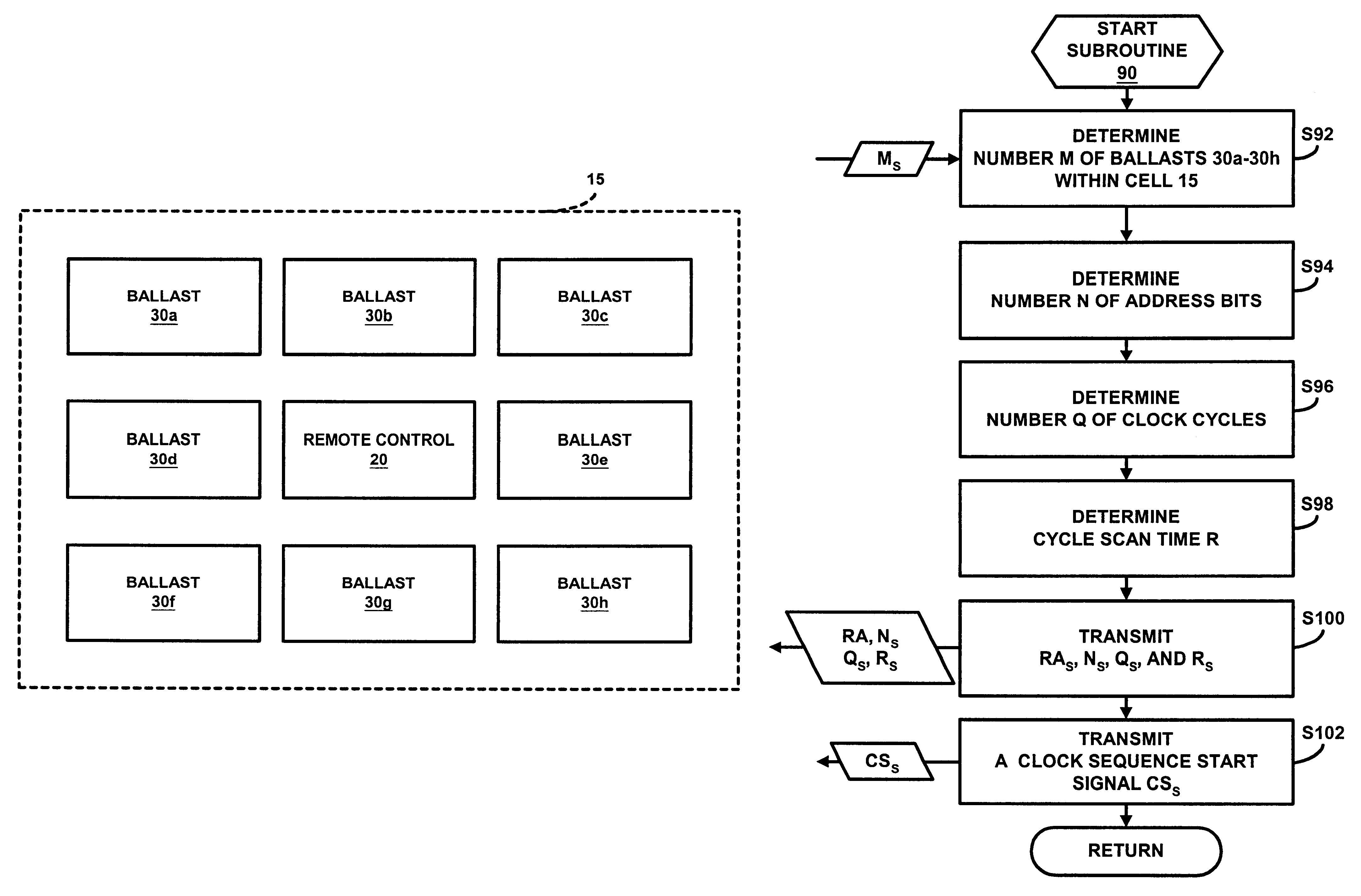
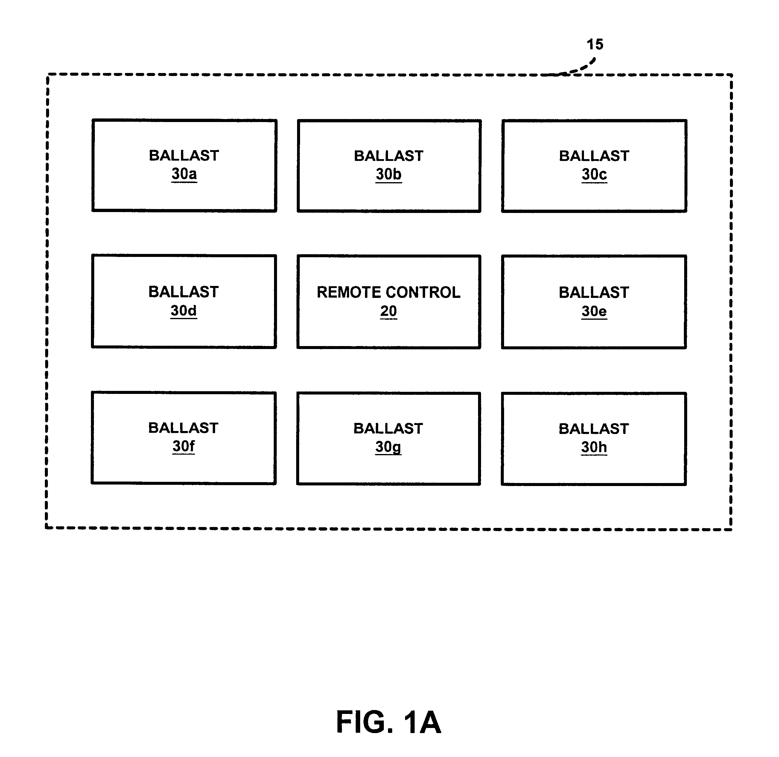
Referring to FIGS. 1A-1C, a cell 15 containing a remote control 20, a ballast 30a, a ballast 30b, a ballast 30c, a ballast 30d, a ballast 30e, a ballast 30f, a ballast 30g, and a ballast 30h is shown in FIG. 1A. Cell 15 represents an area of ballasts 30a-30h intended to be operatively controlled by remote control 20, e.g., a room. In alternative embodiments, cell 15 can contain additional remote controls 20, and more or less ballasts 30.

After installation of ballasts 30a-30h within cell 15, a network address is assigned to each ballasts 30a-30h and each assigned network address is bound to a command of remote control 20 whereby a user of remote control 20 can selectively control ballasts 30a-30h.

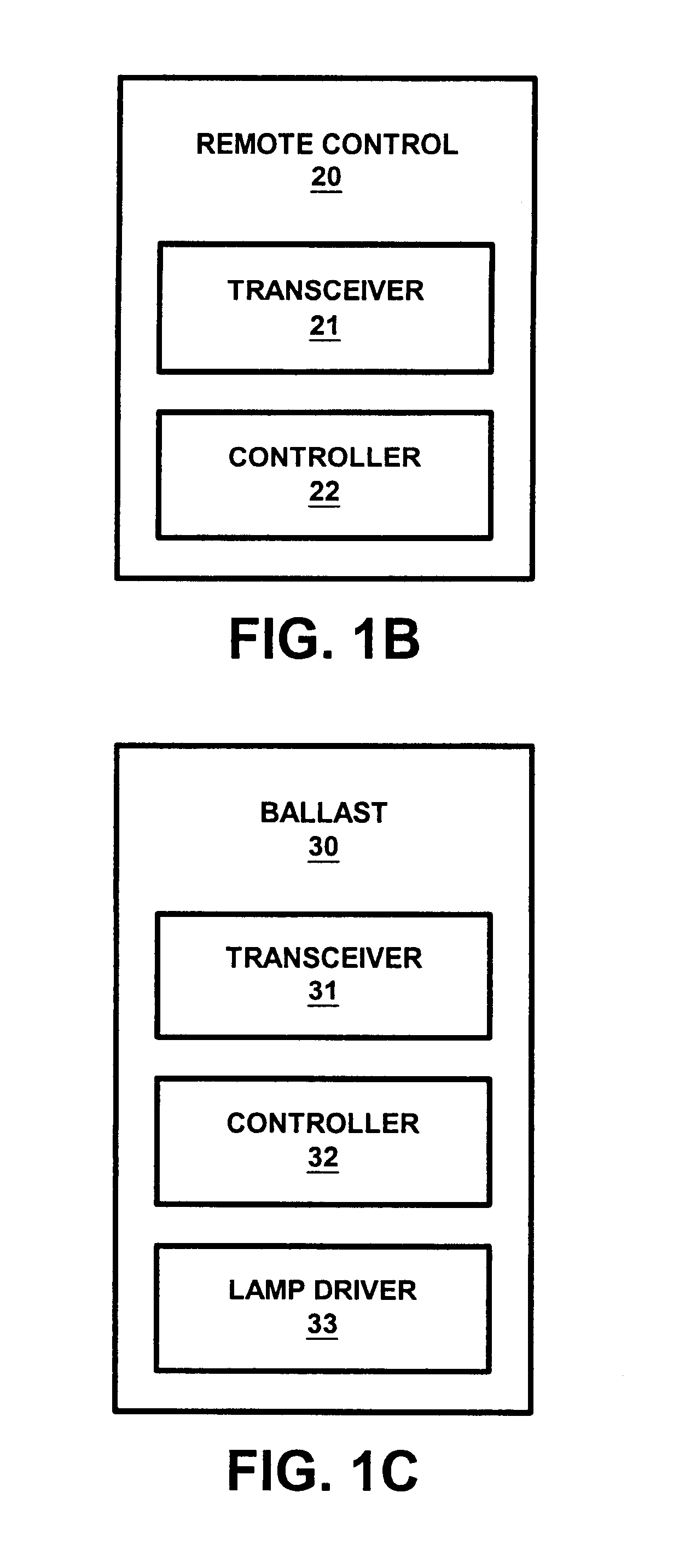
As shown in FIG. 1B, remote control 20 includes a conventional transceiver 21, and a controller 22 in accordance with the present invention. Controller 22 is an electronic circuit comprised of one or more components that are assembled as a common unit. Controller 22 may be comprised of digit...


PUM


Abstract

A system for implementing a method for initializing and binding ballasts is disclosed. The system comprises a remote control having a master controller and the ballasts each having a slave controller. The master controller and the slave controllers are operated to implement routines whereby the master controller generates a clock sequence of a plurality of clock cycles, and the slave controllers randomly generate addresses and direct a transmission of signals indicative of the generated random addresses to the master controller during corresponding clock cycles. In response thereto, the master controller assigns network addresses corresponding to the random addresses as indicated by the corresponding clock cycles. The master controller and the slave controllers are further operated to implement routines for verifying the assigned network addresses and routines for binding each network address to a command of the remote control.

Description

1. Field of the InventionThe present invention generally relates to wireless control of lighting fixtures and lamps. The present invention specifically relates to the assigning and binding of network addresses of ballasts within the fixtures and lamps.2. Description of the Related ArtCurrently, there are infrared wireless control systems and radio frequency wireless control systems for allowing a user to control an operation of a lighting fixture or lamp without the use of a light switch wired directly to the fixture or lamp. Typically, such systems include a remote control having a transmitter and a ballast within each fixture or lamp, each ballast having a receiver. A user operates the remote control to transmit operating commands to a particular receiver of a selected ballast whereby an operation of the selected ballast is controlled. To be able to individually and collectively control each ballast within a cell, each receiver is identified by a unique address that is pre-set wit...

Claims


Application Information

Patent Timeline
Patent Type & Authority Patents(United States)
IPC IPC(8): H05B37/02H04L29/12H05B41/36H04L12/28
CPCH04L29/12254H04L29/1232H04L61/2038H05B41/36H05B37/0245H05B37/0272H05B37/029H04L61/2092H05B47/175H05B47/19H05B47/155H04L61/5038H04L61/5092
Inventor WANG, LINGWACYK, IHOR
Owner SIGNIFY HLDG BV
Why Eureka
Try Eureka