
Roll control system and method for a suspended boom

a control system and boom technology, applied in the field of suspended booms, can solve the problems of difficult to maintain a uniform height at all points of the boom, and achieve the effect of reducing the difficulty of maintenan

Inactive Publication Date: 2004-12-21
NORAC SYST INT
View PDF36 Cites 41 Cited by
  • Summary
  • Abstract
  • Description
  • Claims
  • Application Information

AI Technical Summary

Benefits of technology

"This patent is about a control system for a boom sprayer that automatically adjusts the position of the spray tips to maintain a uniform spray. The system uses sensors to measure the distance between the boom and the ground, and a computer program to calculate the roll position of the boom and adjust it accordingly. This system improves the performance of the boom operator and makes the sprayer more efficient. It also allows for faster operation and better stability. The control system can use a combination of boom position parameters to control the roll position, and real-time operating parameters can be used to adjust the boom roll position. Overall, this patent provides an effective and automated solution for controlling the boom roll position."

Problems solved by technology

Maintaining a uniform height at all points of a boom is a difficult challenge.

Method used


Image

  • Roll control system and method for a suspended boom
  • Roll control system and method for a suspended boom
  • Roll control system and method for a suspended boom

Examples


Embodiment Construction

An embodiment of the roll control system of the invention is illustrated in the drawings and described hereinafter. The function of the roll control system is to control a roll position of a boom rotatably coupled to a support frame, the "roll" position referring to a clockwise or counterclockwise rotation of the boom relative to the support frame.

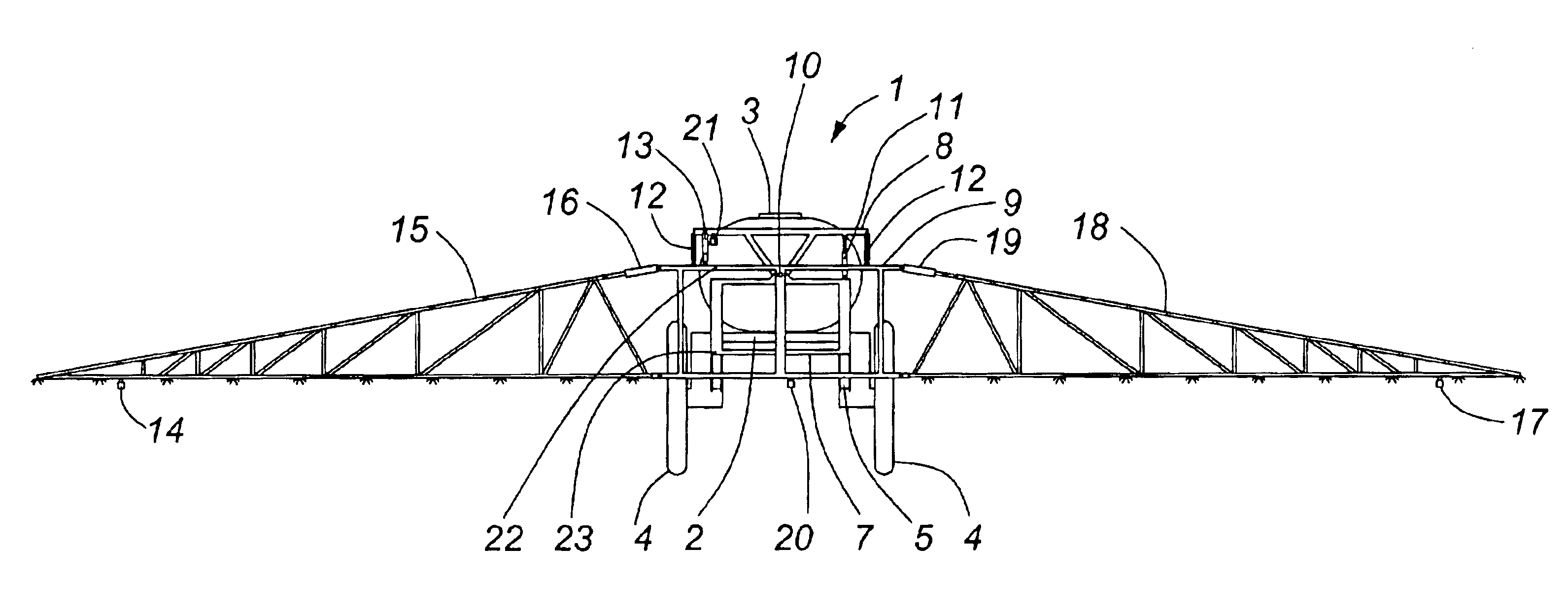
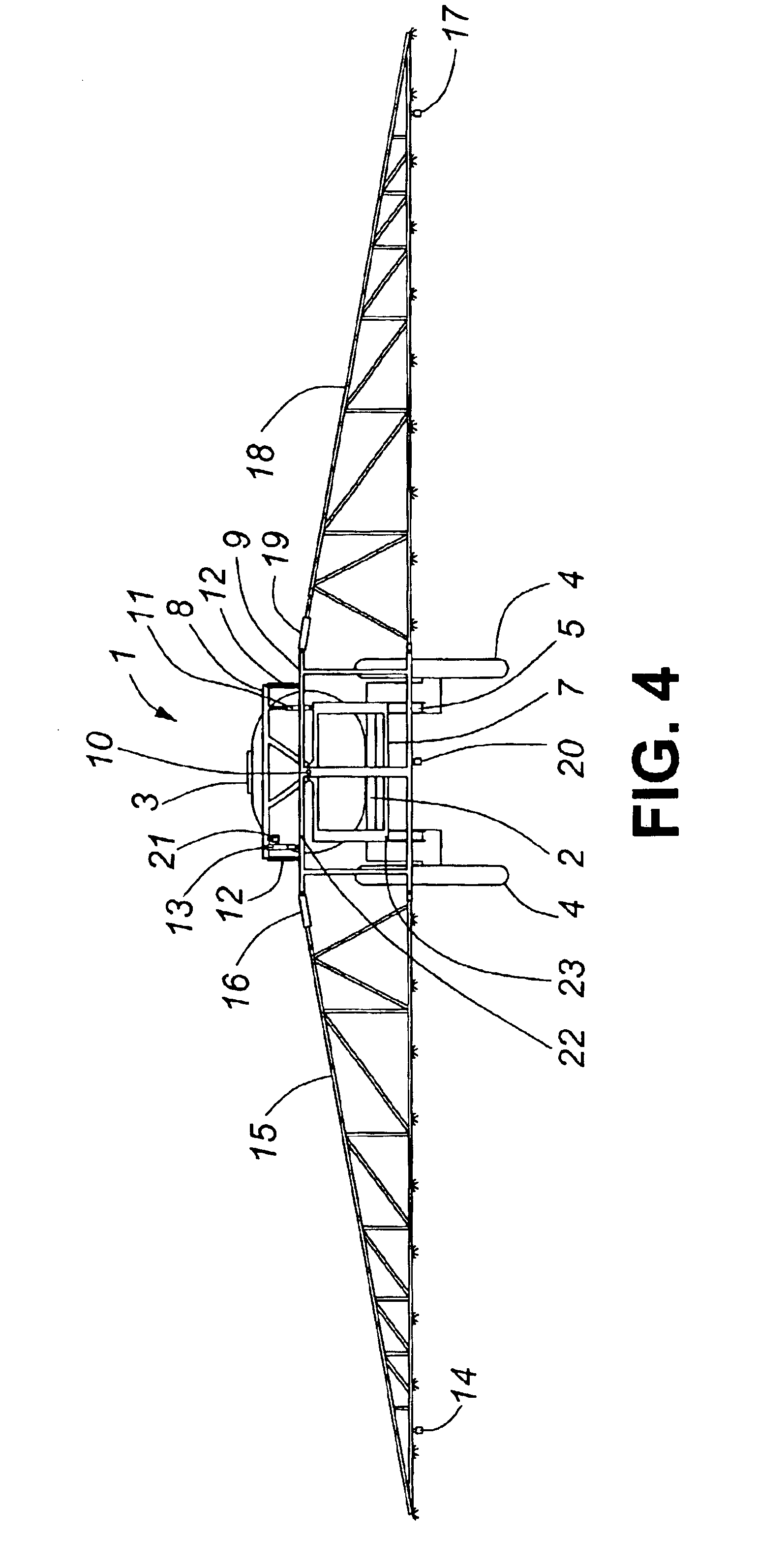
Referring to FIGS. 4, 5 and 6 there is shown a sprayer 1 including a sprayer frame 2 and a sprayer tank 3 which, in this embodiment, are supported by wheels 4 allowing for the forward movement of the sprayer (but it is to be noted that in another embodiment the sprayer could, instead, be a cart which is towed by a self-propelled unit such as a tractor). A parallel linkage 5 and a main boom hydraulic lift cylinder 6 attach at one end thereof to the sprayer frame 2 and at the opposite end thereof to a boom support frame 7. In this embodiment, the overall boom height adjustment illustrated by FIG. 1 is performed by adjusting the lift cylinder...


PUM


Abstract

A roll control system is provided for controlling a roll position of a boom rotatably coupled to a support frame, the boom comprising left and right wing sections (where the roll of the boom refers to a clockwise or counterclockwise rotation of said boom relative to the support frame). A roll control mechanism is configured for rotating the boom relative to the support frame in response to a roll control signal. Wing section position measuring apparatus is configured for producing a right wing signal correlatable to a distance between the right wing section and a rightwing reference position and a left wing signal correlatable to a distance between the left wing section and a left wing reference position. Boom roll position measuring apparatus is configured for producing a boom roll signal correlatable to a roll position of the boom relative to a boom roll reference position. A controller is configured for: (i) identifying a wing section differential value and a boom roll value derived from the right and left wing signals and the boom roll signal, respectively; (ii) identifying a boom roll control error value derived from the wing section differential value and the boom roll value, the boom roll error control value being configured for deriving therefrom the roll control signal. Advantageously, the roll control system of the invention takes into account both the height differential (relative to a ground reference) between the left and right wings and the boom roll position relative to a neutral (reference) position.

Description

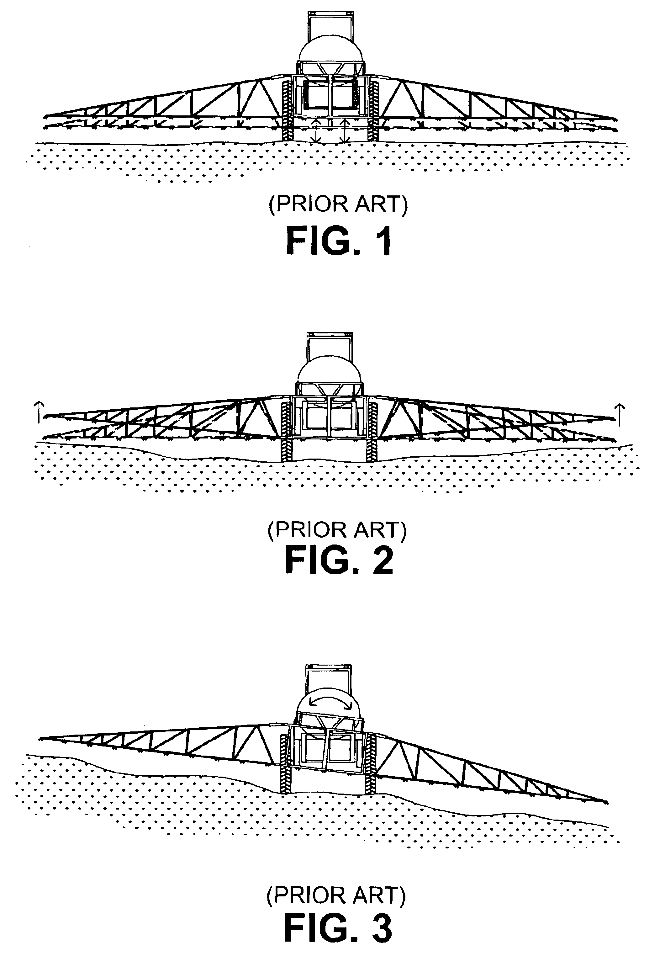
This invention relates generally to the field of control systems for controlling the position of a suspended boom and, more specifically, to a control system for automatically controlling the roll of a boom.BACKGROUND TO THE INVENTIONSuspended booms are used in many different industries for different purposes. In the agricultural industry, for example, a suspended boom sprayer is commonly used for the application of pesticides, herbicides and fertilizers. Spray tips are mounted to the sprayer boom at a predetermined spacing to promote an even application of the material being applied. In order to achieve a reasonably uniform application of such material it is necessary that the spray tips be maintained at a constant (or near constant) distance from the ground or vegetation to which the material is being applied. Generally, the spray tips used for these applications are designed for use at a specific height for optimum performance and application uniformity.Maintaining a uniform heig...

Claims


Application Information

Patent Timeline
Patent Type & Authority Patents(United States)
IPC IPC(8): B05B15/08B05B15/00B05B15/10B05B1/14B05B1/20G06F19/00A01M7/00B05B15/68G01S19/54
CPCA01M7/0057
Inventor STRELIOFF, WILLIAMHOCKLEY, DEANLEE, GORDON
Owner NORAC SYST INT
Learn More