Shower curtain closure

Inactive Publication Date: 2005-01-04
KIRSOPP DEREK
View PDF4 Cites 14 Cited by
  • Summary
  • Abstract
  • Description
  • Claims
  • Application Information

AI Technical Summary

Benefits of technology

The inner channel is provided with a ridged longitudinal handle integrally formed therewith for moving the shower curtain in and out of the outer channel. In effect, one has erected a portable shower enclosure with an easily closable sliding door. Since the inner channels can both open and close the curtain, the user may enter or exit from either end. If desirable, weights may be

Problems solved by technology

Often the typical shower curtain does not adequately prevent water from spilling onto the bathroom floor as the curtain moves away from the shower walls due to the decreased pressure of air entrained with the water spray.
In addition, this effect can be due to an open window or door blowing the curtain.
A further problem arises since

Method used


Image

  • Shower curtain closure
  • Shower curtain closure
  • Shower curtain closure

Examples


Example

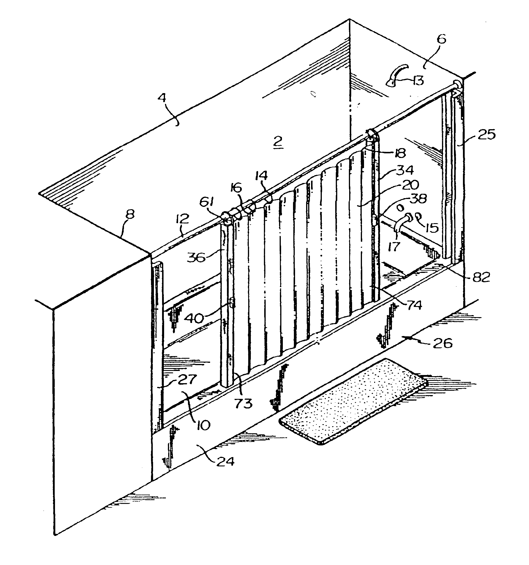
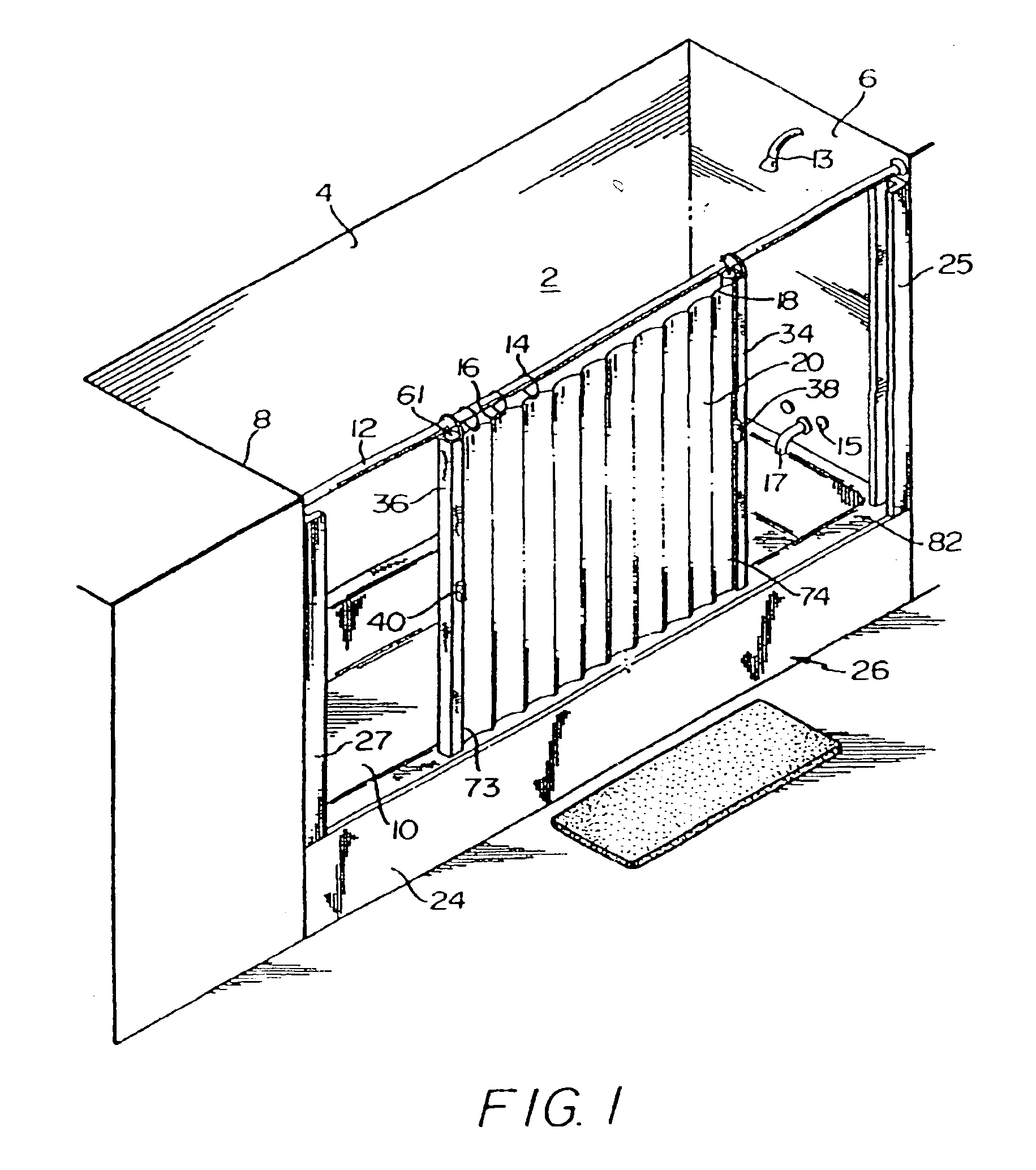
Referring now to the drawings and particularly to FIG. 1, a bathtub enclosure is indicated generally at 2 and includes back wall 4, side walls 6 and 8, an open front 10 spanned by shower curtain rod 12, shower nozzles 13, faucets 15, spigot 17 and the outer bathtub wall 24.

A conventional curtain rod 12 spans the space between the walls 6 and 8 and includes the suspension rings 14 which are fitted into apertures 16 in the top edge18 of the curtain 20. The curtain 20 is in touching relationship with the top edge 82 of the outer wall 24 of the tub 26 or the inner surface of outer wall 24.

The device 2 of the present invention includes the U-shaped outer vertical channels 25 and 27 on the opposed walls 6 and 8 respectively, secured thereto by screws or conventional adhesive means.

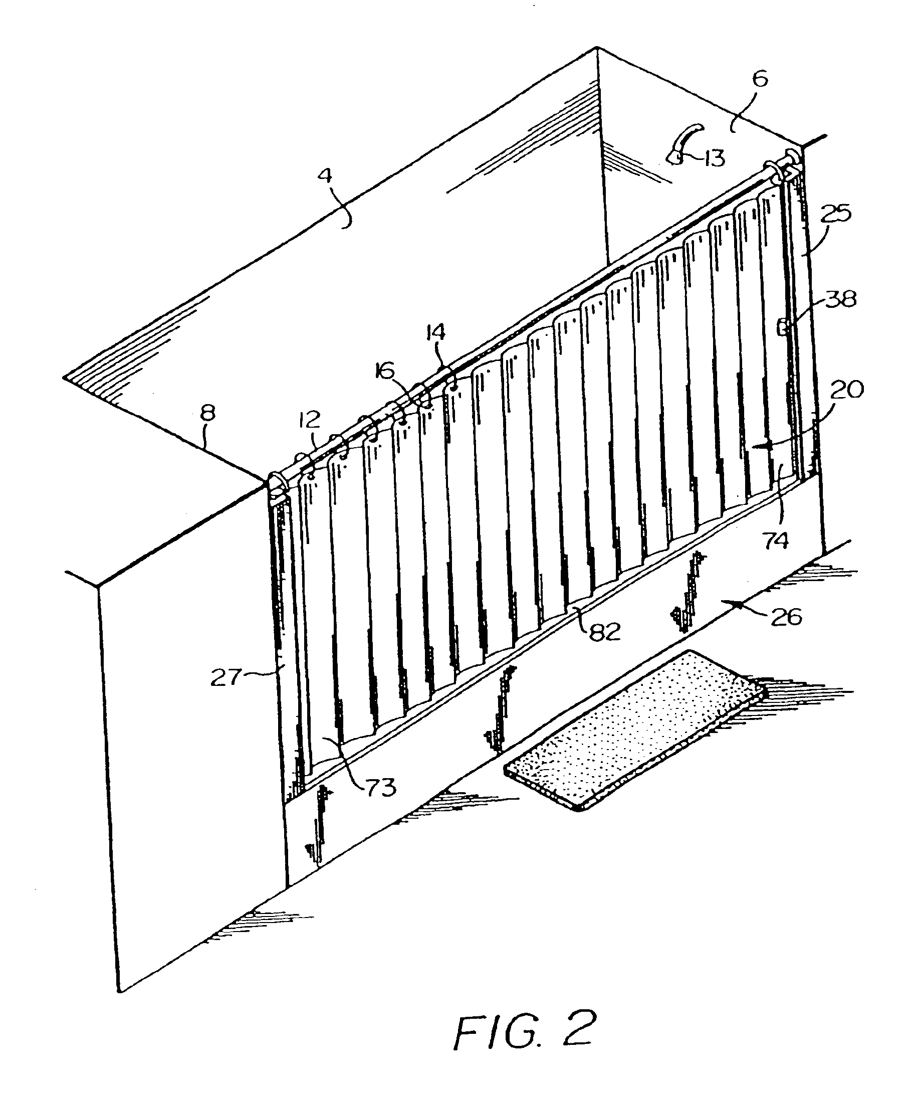
Each vertical edge 73 and 74 of the curtain 20 is secured in a U-shaped inner channel 34 and 36 by one of several means.

The curtain 20 is shown drawn closed in FIG. 2 with the U-shaped inner channels 34 and 36 a...


PUM


Abstract

A system is provided for converting a bathtub area into an enclosed substantially waterproof shower enclosure by means of adding or modifying the shower curtain installation by providing inner closure channels at each end of the shower curtain as well as corresponding outer retention channels that are easily fixed onto opposed walls in the bathtub enclosure for sealingly receiving the side edges of the curtain in a waterproof relationship. Each end of the shower curtain is retained within a vertically disposed U-shaped inner channel having longitudinal ridges within the U-shaped channel for retention of a flexible slit grommet spline or locking rod running lengthwise. The edge of the shower curtain is inserted into the flexible spline or locking rod which is then pressed fitted into the inner U-shaped channel. The curtain is securely retained by friction between the spline and the internal longitudinal ridges and walls of the U-shaped inner channel which is secured to the outer retention channel in similar fashion.

Description

BACKGROUND OF THE INVENTION1. Field of the InventionThis invention relates to closures for showers and bathtubs and more specifically to a shower curtain closure assembly.2. Description of the Prior ArtThe device of the present invention is related to an improved closure device for shower curtains. The device may also be used in connection with tarps, curtains, and covers and other related fields where a closing device for a curtain-like structure is employed.Utilization of shower curtains to try to prevent water from the shower from going outside the shower enclosure at the edges is well known. Shower curtains are often pulled away from the edge of the shower or tub enclosure by the vacuum created by the velocity of the water from the shower head according to well-known phenomena.Often the typical shower curtain does not adequately prevent water from spilling onto the bathroom floor as the curtain moves away from the shower walls due to the decreased pressure of air entrained with ...

Claims


Application Information

Patent Timeline
IPC IPC(8): A47K3/38A47K3/28
CPCA47K3/38
Inventor KIRSOPP, DEREK
Owner KIRSOPP DEREK
Why Eureka
Try Eureka