

Projector optical system, projector optical engine, and projection method
- Summary
- Abstract
- Description
- Claims
- Application Information
AI Technical Summary
Benefits of technology
Problems solved by technology
Method used
Image

Examples
first preferred embodiment
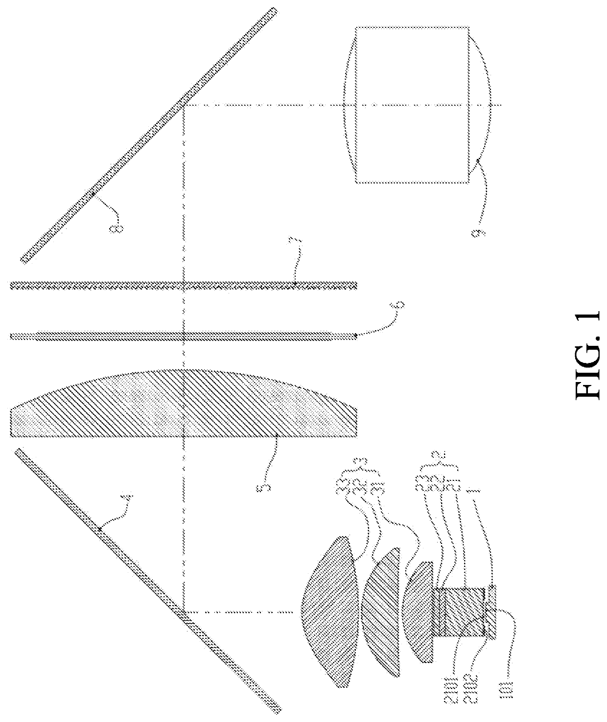
[0057]As shown in FIGS. 1-3, according to a first preferred embodiment, a projector optical system is provided, comprising a LED light source 1, an optical rod polarization conversion module 2, an overlapped lens module 3, a first mirror 4, a focusing lens 5, a LCD (Liquid Crystal Display) light valve 6, a field lens 7, a second mirror 8 and a projection lens 9, which are sequentially arranged according to a traveling direction of lights.
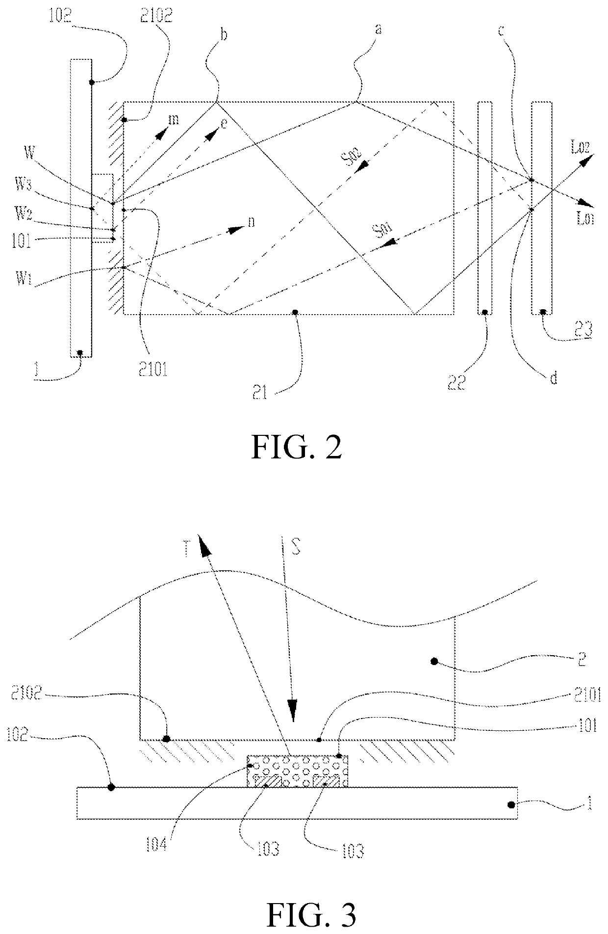
[0058]In the first preferred embodiment, lights (natural lights) emitted from a light emitting surface 101 of the LED light source 1 is incident on the optical rod polarization conversion module 2 for integration and polarization conversion through a light transmitting part 2101 of an integration rod 21, and then further incident on the overlapped lens module 3; multiple light source images on an emergent surface of the integration rod 21 are superimposed on the LCD light valve 6, so as to realize uniform illumination to the LCD light valve 6; the f...
second preferred embodiment
[0068]As shown in FIGS. 1-3, in the second preferred embodiment, the integration rod 21 is a solid glass rode, and the sizes of the incident surface and the emergent surface of the integration rod are same; the polarized light modulation plate 22 adopts a phase plate; the brightening polarizer 23 adopts a wire grid polarizer; wherein: a necessary air gap exists between an emergent surface of the phase plate and an incident surface of the wire grid polarizer.
[0069]In the second preferred embodiment, the process of reaching the wire grid polarizer of the lights emitted by the LED light source 1 is not repeated herein.
[0070]Referring to the first preferred embodiment, the light S01 is reflected by the brightening polarizer 23; after passing through the polarized light modulation plate 22, a phase of the light S01 is randomly changed, and the light S01 enters the integration rod 21, is reflected at the W1 point on the reflecting part 2102, enters the integration rod 21 again, and passes...
third preferred embodiment
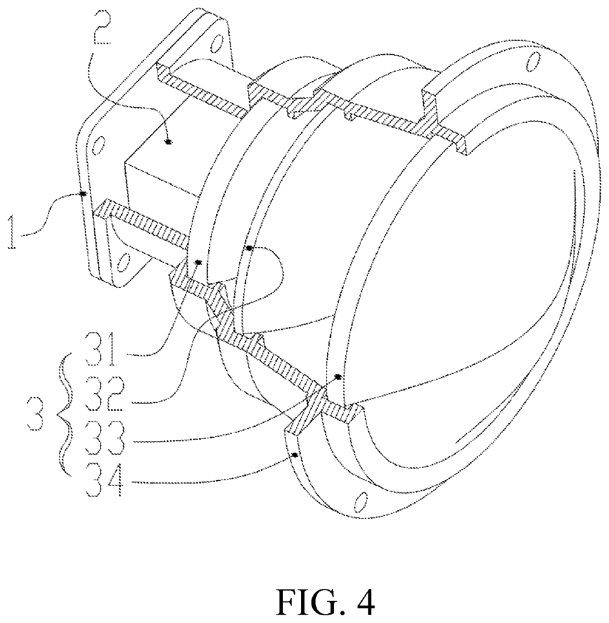
[0083]According to the third preferred embodiment, the relatively precise assembly is required to achieve the relatively good photoelectric efficiency, especially the assembly precision of the LED light source 1, the optical rod polarization conversion module 2 and the overlapped lens module 3, as shown in FIGS. 4-6.
[0084]As shown in FIGS. 4-5, the first lens 31, the second lens 32 and the third lens 33 of the overlapped lens module 3 are arranged in a precise sleeve 34; the LED light source 1, the optical rod polarization conversion module 2 and the overlapped lens module 3 are integrated to form a precise illumination assembly module, so that more flexible process deployment can be achieved during production. After achieving the relatively good coaxiality and precision, the above optical components are arranged on an optical engine cover 13, so that the structural precision requirements on the optical engine cover 13 are decreased and the cost is reduced.
[0085]Furthermore, FIG. 5 ...
PUM
 Abstract
Description
Claims
Application Information