
Assist grip

Inactive Publication Date: 2005-01-04
NIFCO INC
View PDF17 Cites 24 Cited by
  • Summary
  • Abstract
  • Description
  • Claims
  • Application Information

AI Technical Summary

Benefits of technology

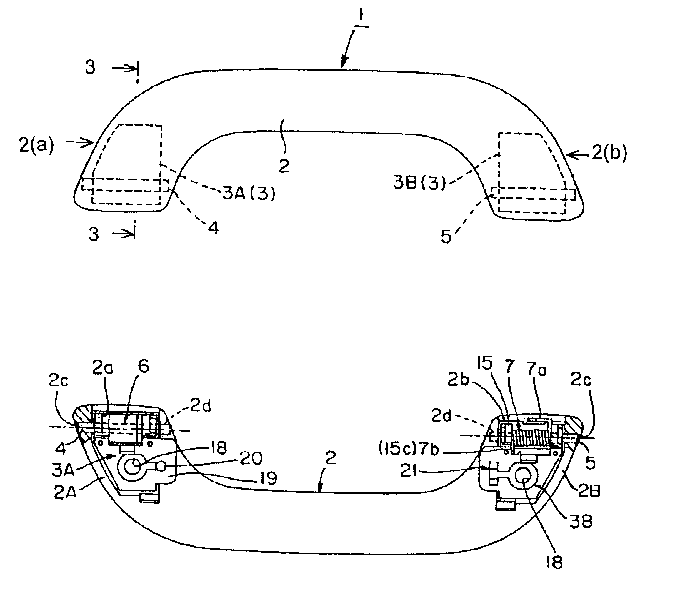
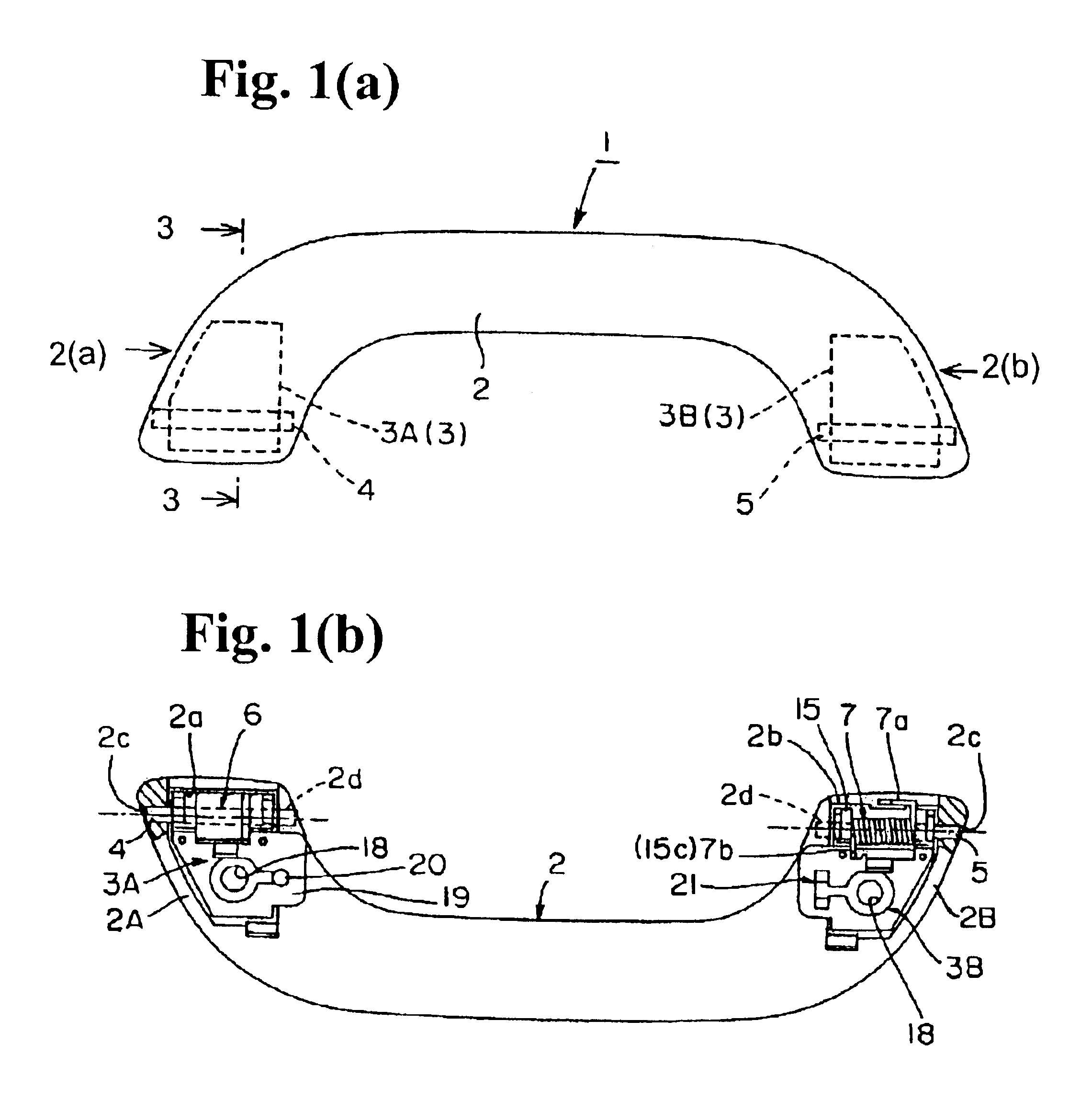
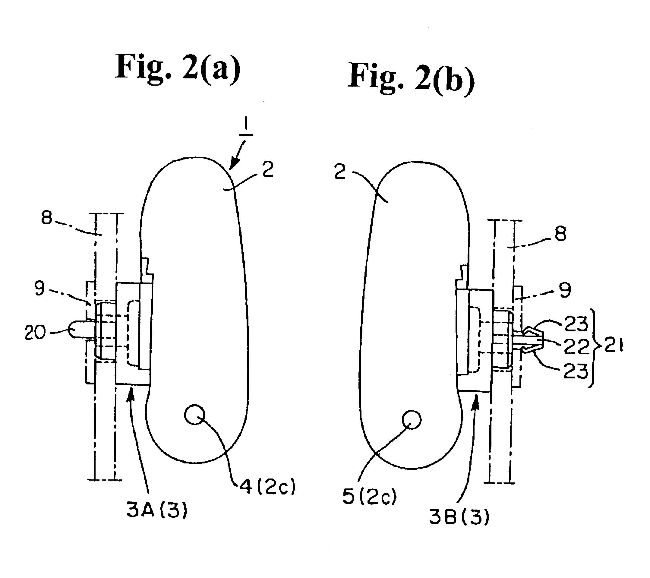
In order to achieve the above-mentioned objects, the first aspect of the invention provides an assist grip having supporting members on both sides of a main portion of the grip. The assist grip can rotate to switch between a non-operational position retracted along an attaching portion of a vehicle and an operational position projecting inside the vehicle through the supporting members. After the supporting members are attached temporarily in the attaching portion of the vehicle, a permanent fixing member fixes the assist grip to the attaching portion. The attaching portion of the vehicle includes two holes with different shapes, namely the first temporary attaching hole and the second temporary attaching hole, at positions corresponding to the supporting members. One of the supporting members includes a pole protrusion for freely inserting and pulling out of the first temporary attaching hole. The other of the supporting members includes an elastic protrusion that can not be pulled out once inserted in the second temporary attaching hole with a specific pressure. When the grip main portion is rotated by a specific angle while the pole protrusion of the one supporting member is pulled out from the first temporary attaching hole, the elastic protrusion can be pulled out freely from the second temporary attaching hole.
In the above-mentioned first aspect of the invention, the assist grip is designed from a view of a temporary attaching structure, and is attached temporarily by pushing toward the attaching portion of the vehicle from the front. Thus, once attached temporarily, the assist grip never come out due to the engagement between the elastic protrusion and the second temporary attaching hole, even if the assist grip receives a large vibration, etc. Also, when the assist grip needs to be taken off, the elastic protrusion of the other supporting member can be easily taken off from the second temporary attaching hole after the pole protrusion in the one of the supporting member is pulled out from the first temporary attaching hole and the grip main portion is rotated by a predetermined angle.
This is an advantage, for example, for a vehicle interior assembly line to conduct two separate processes, i.e. a temporary attaching process of attaching several assist grips to the corresponding positions inside the vehicle, and a permanent attaching process of fixing the grips by the permanent attaching members. Furthermore, it is relatively easy to remove the grips during the maintenance or recovery upon scrapping the motor vehicle.
The invention also provides modifications of the shapes of the first temporary attaching hole, the second temporary attaching hole, the pole protrusion and the elastic protrusion. However, the invention is not limited to the modifications, and can achieve the objects as long as the following features are met. The pole protrusion can be inserted and pulled out freely from the first temporary attaching hole. The elastic protrusion becomes incapable of being pulled out from the second temporary attaching hole when pushed in the second temporary attaching hole, and at the same time, the elastic protrusion can be pulled out easily from the second temporary attaching hole when the grip main portion is rotated by a predetermined angle.
The second aspect of the invention provides the assist grip from a viewpoint of the whole structure of the supporting member. The assist grip has the following structural and operational features. The supporting member is integrally formed of the cover portion for opening and closing and the engagement device. After the supporting member is tightened with the permanent attaching members (screw, bolt, etc.), the recessed portion of the base portion is covered with the cover portion. Thus, the good appearance and reliability are maintained, thereby increasing a commercial value without increasing the number of the parts.
Also, the third aspect of the invention provides modifications of the protrusion for the temporary attaching and the engagement device. The protrusion is designed, for example, to maintain the appearance feature by controlling the size of the recessed portion of the base portion, and to give a stable attachment by increasing an area abutting against the attaching portion of the vehicle. The engagement device is designed, for example, to install easily without spoiling the appearance.

Problems solved by technology

(1) In an operation of installing the grip inside the vehicle, for example, after a plurality of the assist grips 50 is fixed temporarily as being placed in specific positions, the grip is installed by tightening the screws 58 and so on. In the conventional structure, the pole-like protrusion 55 is inserted into the temporary attaching hole to fix temporarily. However, the protrusion 58 may easily come out from the temporary attaching hole when the grip is installed with the permanent attaching member such as the screw 58 etc., or when fixed by the screw 58, etc., even though an external diameter of the protrusion 55 is enlarged and pushed in the temporary attaching hole tightly.
However, in this structure, a manufacturing cost may be high due to the complicated structure, and the assist grip is difficult to remove from the attaching portion in the compartment of the vehicle during maintenance or for recovery upon scrapping the vehicle, and so on.
Therefore, the appearance of the assist grip becomes bad in the operational position and gives an unpleasant feeling, or the credibility of the merchandise itself is deteriorated.

Method used


Image

  • Assist grip
  • Assist grip
  • Assist grip

Examples


Embodiment Construction

Hereunder, embodiments of the invention will be explained according to the accompanying drawings. FIGS. 1(a) and 1(b) show an embodiment of the assist grip, and FIG. 1(a) shows a frontal view, and FIG. 1(b) shows a rear view with a partial sectional view. FIGS. 2(a) and 2(b) are right and left side views showing the assist grip seen from directions 2(a) and 2(b) in FIG. 1(a). FIG. 3 is a sectional view along line 3—3 in FIG. 1(a) showing the assist grip in an installed state. FIGS. 4(a) and 4(b) are perspective views showing an appearance of the assist grip in a non-operational position (state) and an operational position (state). FIGS. 5(a)-5(c) are views showing a detailed structure of one end of the assist grip, wherein FIG. 5(a) is a view showing a supporting member in an open state of the cover portion, FIG. 5(b) is a view showing a relation between a main portion of the assist grip and the supporting member, and FIG. 5(c) is a view showing a state that the supporting member is...


PUM


Abstract

A grip main portion includes supporting members disposed on both sides thereof. An assist grip can be rotated to switch between a non-operational position and an operational position projected into a compartment through the supporting members. An attaching portion of the compartment is provided with the first and second temporary attaching holes. One of the supporting members is provided with a pole protrusion passing freely through the first temporary attaching hole. The other supporting member is provided with an elastic protrusion to be engaged when inserted into the second temporary attaching hole. The elastic protrusion can be pulled out from the second temporary attaching hole when the grip main portion is rotated by a predetermined angle with the pole protrusion being pulled out from the first temporary attaching hole.

Description

BACKGROUND OF THE INVENTION AND RELATED ART STATEMENTThe present invention relates to an assist grip installed in a vehicle, especially to an assist grip that can rotate to switch between non-operational and operational positions.An example of a conventional assist grip has been disclosed in Japanese Patent Publication (KOKAI) No. 09-156409, as shown in FIGS. 10(a) and 10(b). In an assist grip 50, a main body 51 includes supporting members 52 assembled on both, sides. By means of the supporting members 52, the assist grip 50 can rotate to switch positions between a non-operational position retracted along an attachment portion inside a vehicle and an operational position projecting inside the vehicle. As shown in FIG. 10(b), each of the supporting members 52 is integrally formed of a recessed base portion 53, a through hole 54 provided at a back wall of the base portion 53, a protrusion 55 for temporary assembly, and a connection portion 56 provided under the base portion 53. The su...

Claims


Application Information

Patent Timeline
IPC IPC(8): B60N3/02E05B1/00
CPCB60N3/023E05B1/0015B60N3/026Y10T16/44
Inventor YAMAMOTO, YASUOSUGIYAMA, TAMOTSU
Owner NIFCO INC
Features
  • Generate Ideas
  • Intellectual Property
  • Life Sciences
  • Materials
  • Tech Scout
  • Unparalleled Data Quality
  • Higher Quality Content
  • 60% Fewer Hallucinations
Learn More