System for using a 2-axis magnetic sensor for a 3-axis compass solution

a magnetic sensor and solution technology, applied in the field of electronic compasses, can solve the problem of not having enough space for a 3-axis magnetic sensor

Inactive Publication Date: 2005-01-04
HONEYWELL INT INC
View PDF5 Cites 195 Cited by
  • Summary
  • Abstract
  • Description
  • Claims
  • Application Information

AI Technical Summary

Benefits of technology

In one aspect, a tilt-compensated compass system is disclosed. The system includes a 2-axis magnetic sensor, a tilt sensor, a memory, and a processor. The system also includes at least one value for the Earth's field strength stored in the memory. The memory may also store a set

Problems solved by technology

In some compass applications, however, such as cell phones and watches, not enough space is available for a 3

Method used


Image

  • System for using a 2-axis magnetic sensor for a 3-axis compass solution
  • System for using a 2-axis magnetic sensor for a 3-axis compass solution
  • System for using a 2-axis magnetic sensor for a 3-axis compass solution

Examples


Embodiment Construction

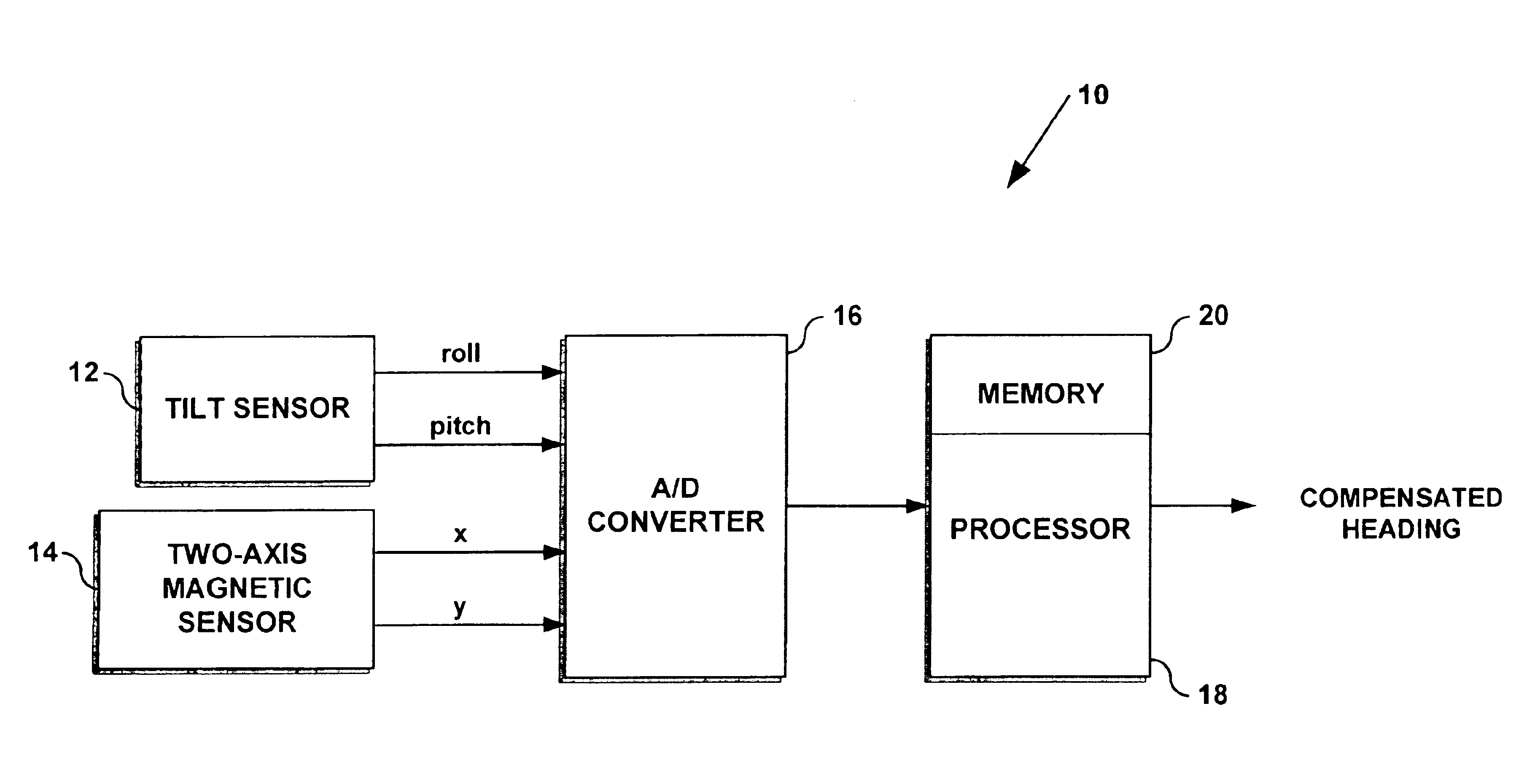
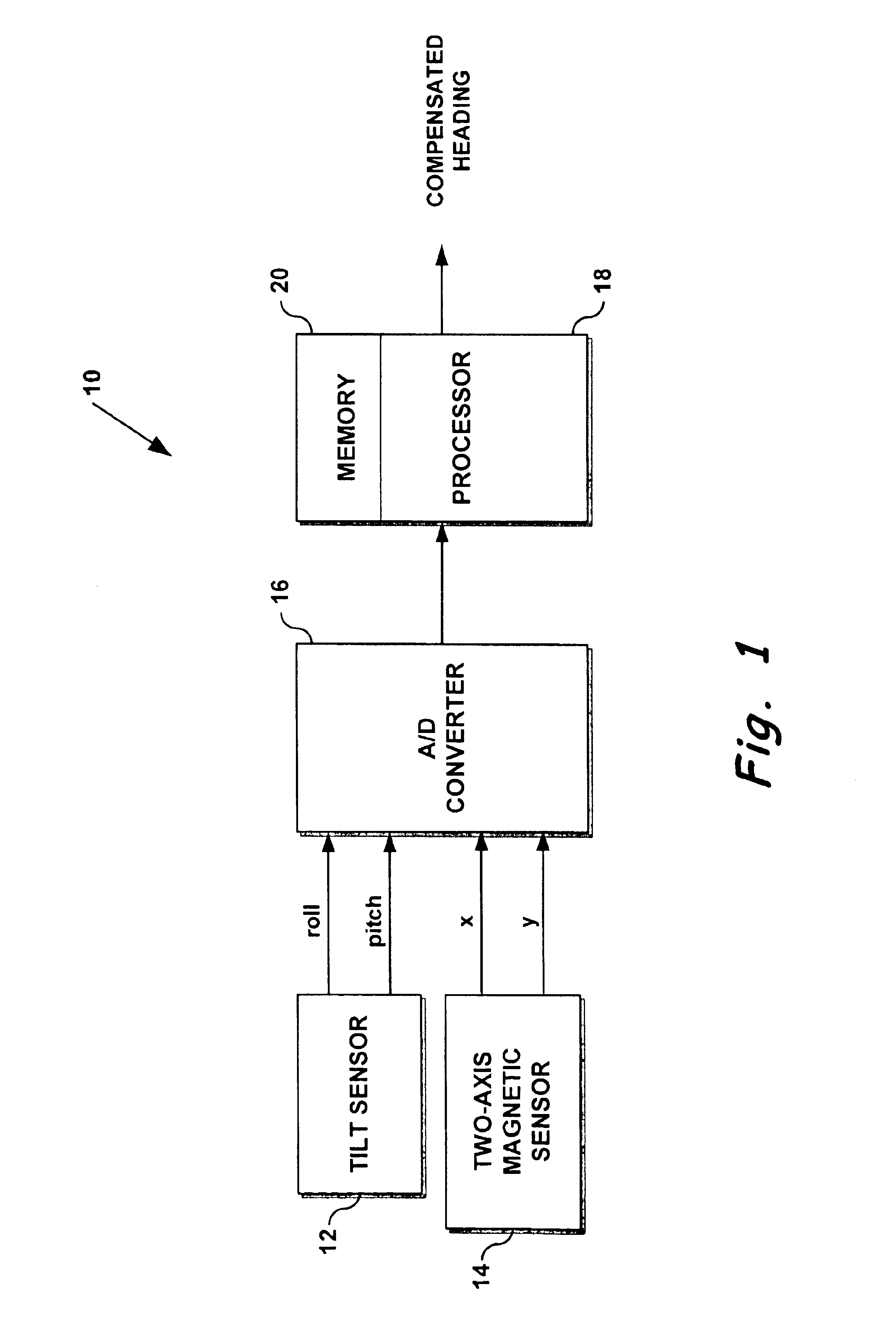
In exemplary embodiments, electronic compasses use sensors capable of producing an electrical signal that is proportional to the direction of the Earth's magnetic field. For highly miniaturized recreational electronic compasses that provide a readout of 8 compass points (or more), a system must be able to resolve direction to the nearest 16°, which is easily within the sensitivity of many magnetic sensors, such as anisotropic magnetoresistive sensors (AMRs), Hall-effect, GMRs, inductive coil, and flux-gate sensors.

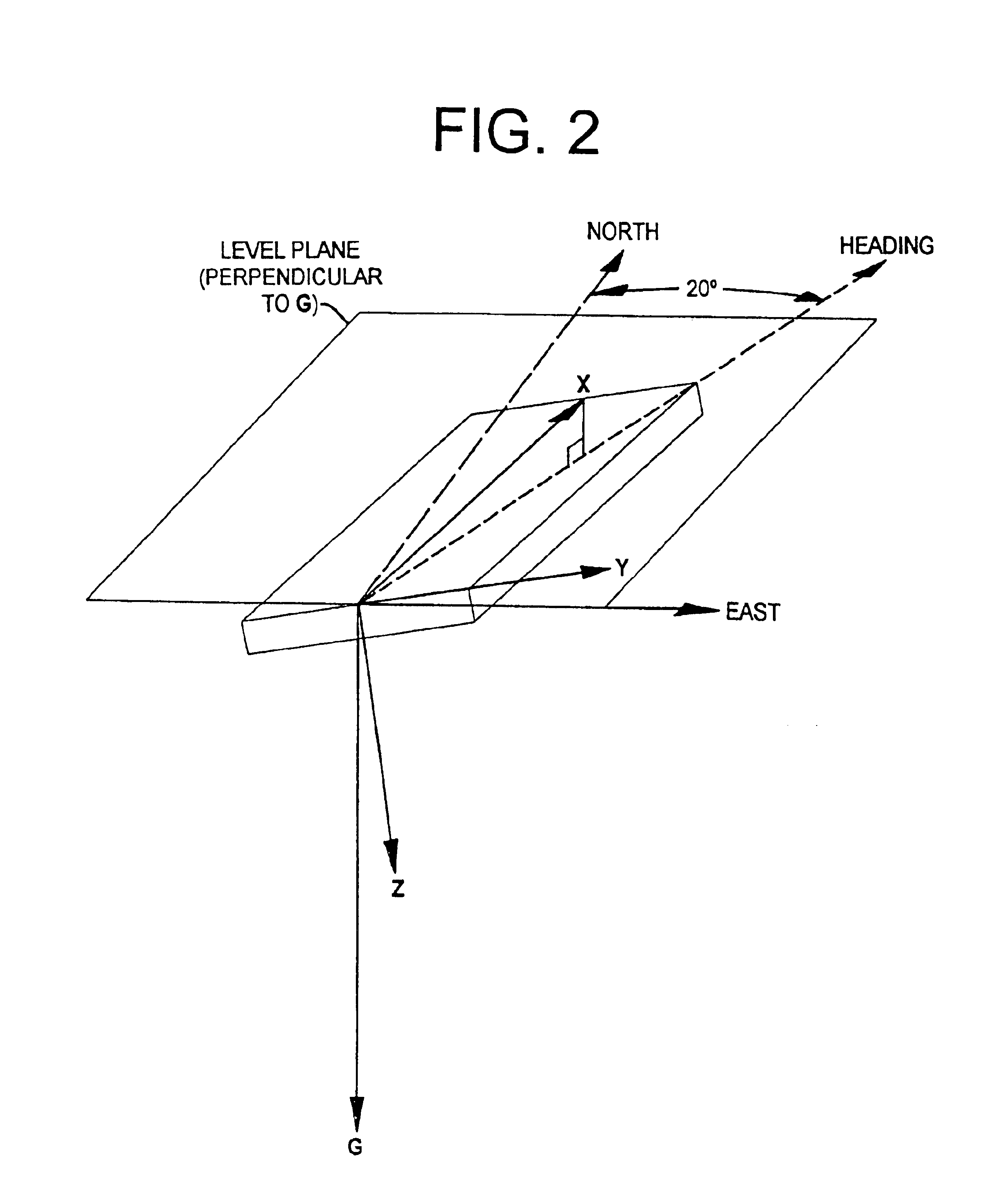
Typically, to compensate for compass tilt in order to provide at least 16° accuracy, a 3-axis magnetic sensing system and a tilt sensor are required to solve equations (1), (2), and (3). This is because equations (2) and (3), as can be seen, require magnetic field measurements in the x-, y-, and z- directions and tilt measurements in 2 axes. By mathematically calculating field strength along one axis (such as the z-axis), however, a 2-axis, rather than a 3-axis magnetic fi...


PUM


Abstract

A tilt-compensated electronic compass can be realized by calculating rather than measuring Earth's magnetic field component Z in a direction orthogonal to the two measurement axes of a 2-axis magnetic sensor. The orthogonal component Z can be calculated using a stored value for the Earth's magnetic field strength applicable over a wide geographic region. The calculation also requires using measured field values from the 2-axis sensor. Once Z is known, and using input from a 2-axis tilt sensor, compensated orthogonal components X and Y can be calculated by mathematically rotating the measured field strength values from a tilted 2-axis sensor back to the local horizontal plane. Thus, a very flat and compact tilt-compensated electronic compass is possible.

Description

FIELDThe present invention relates generally to compasses, and more particularly, to electronic compasses.BACKGROUNDFor centuries, navigators and others have indirectly used the Earth's magnetic field to determine direction. This is possible because the magnetic field has a component parallel to the Earth's surface that always points toward magnetic north, and this north-indicating component can be detected with a compass. The magnetic field can be approximated with a dipole model where the field points down toward north in the northern hemisphere, is horizontal and pointing north at the equator, and points up toward north in the southern hemisphere.The magnitude of the Earth's magnetic field remains somewhat constant over fairly large areas, and ranges from about 0.4 to 0.6 gauss over most of the northern hemisphere. Solid-state electronic devices are now sensitive enough to easily measure the Earth's magnetic field. The accuracy of electronic compasses is somewhat dependent on the...

Claims


Application Information

Patent Timeline
IPC IPC(8): G01C17/00G01C17/38
CPCG01C17/38G01C17/00
Inventor WAN, HONG
Owner HONEYWELL INT INC
Why Eureka
Try Eureka