Body construction of electric car

Inactive Publication Date: 2005-01-04
JAPAN SCI & TECH CORP
View PDF13 Cites 26 Cited by
  • Summary
  • Abstract
  • Description
  • Claims
  • Application Information

AI Technical Summary

Benefits of technology

In view of the above-mentioned problems, an object of the present invention is to provide a body construction for an electric car having a flat floor and allowing batteries to be easily installed therein and removed therefrom and to be accommodated under the floor in a space-effective manner, with rational wiring of the power lines.

Problems solved by technology

However, the above-mentioned construction has drawbacks that, since a large number of batteries are accommodated in a row in each long frame, when one of the batteries in the row malfunctions, it is time-consuming to replace the malfunctioning battery with a new one, and also since each power line must be led from the front end or rear end battery, power lines for feeding power to drive motors remote from the batteries become longer and also their wiring becomes complicated.

Method used


Image

  • Body construction of electric car
  • Body construction of electric car
  • Body construction of electric car

Examples


Embodiment Construction

Embodiments of the present invention will be described in detail with reference to the accompanying drawings.

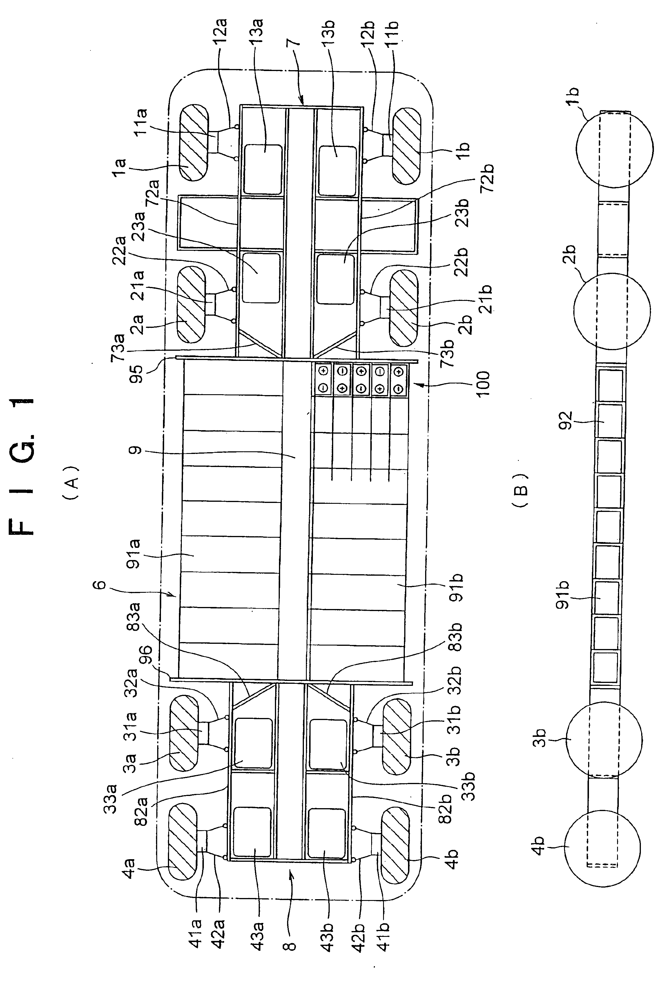
As shown in FIGS. 1A, 1B and 2, the first embodiment provides a chassis 6 for an eight-wheel-drive electric car, having front front-wheels 1a and 1b, front rear-wheels 2a and 2b, rear front-wheels 3a and 3b, and rear rear-wheels 4a and 4b and drive motors (in-wheel motors) 11a and 11b, 21a and 21b, 31a and 31b, and 41a and 41b respectively built in the corresponding wheels.

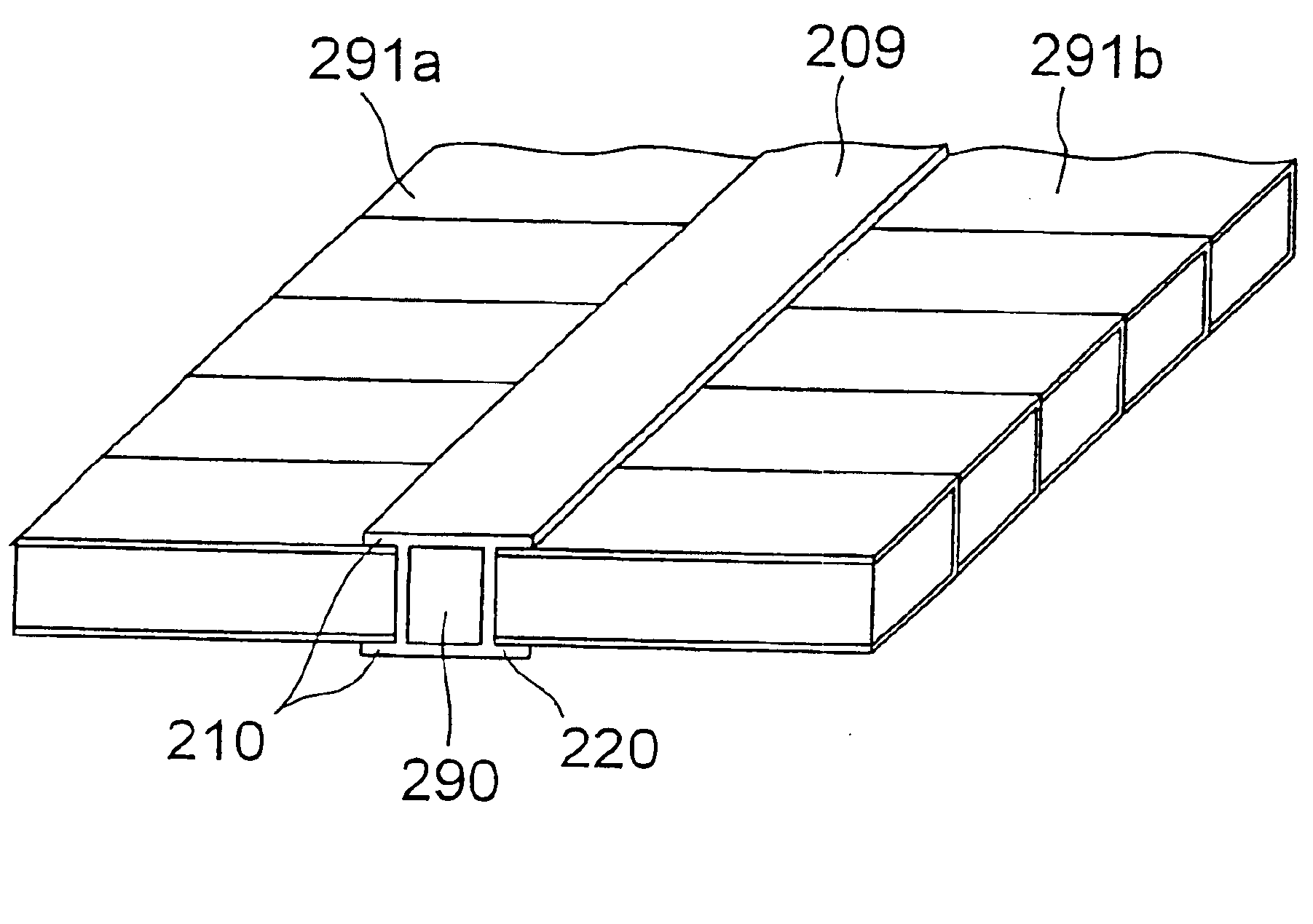
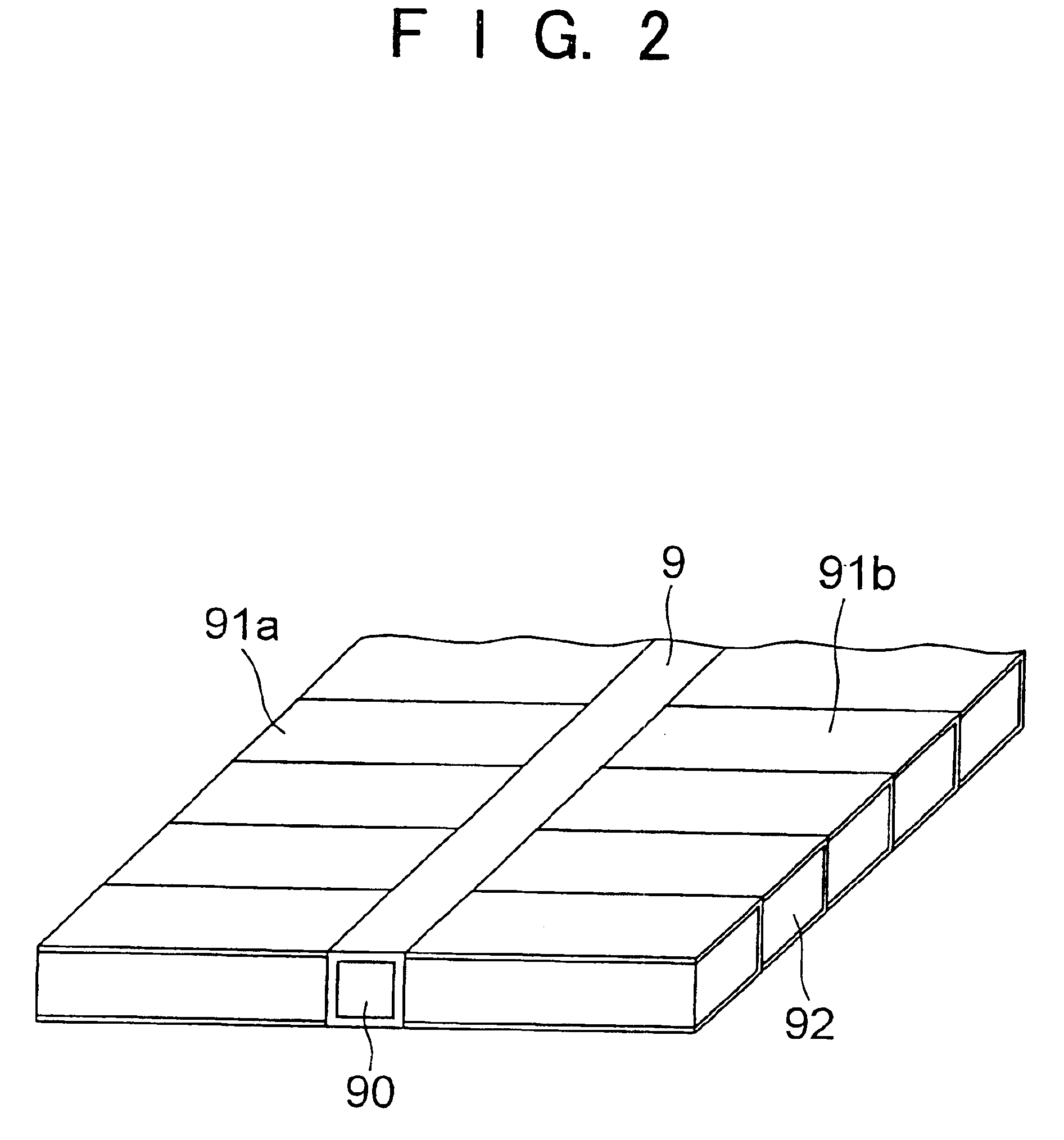
The skeleton of the chassis 6 is formed of a front wheel frame 7, a rear wheel frame 8, and a backbone member 9 extending between the frames 7 and 8 and rigidly connecting the frames 7 and 8 with each other.

The front wheel frame 7 made from a structural member such as a steel channel is formed by frame members 72a and 72b, the former having suspension mechanisms 12a and 12b fixed thereto for respectively suspending the front front-wheels 1a and 1b and the latter having suspension mechanisms 22a and 22b fixe...


PUM


Abstract

The present invention provides a body construction for an electric car having a flat floor and allowing batteries to be easily mounted therein and removed therefrom and to be accommodated under the floor in a space-effective manner, in which power lines are rationally wired. The batteries feed power to a plurality of in-wheel motors. A front wheel frame supporting the front wheels and a rear wheel frame supporting the rear wheels are coupled by a backbone member having an approximately rectangular hollow cross-section, and pluralities of battery-accommodating hollow frames connect perpendicular to the right and left side surfaces of the backbone member, so as to lie parallel to each other.

Description

TECHNICAL FIELDThe present invention relates to a body construction of an electric car, and in particular, it relates to a construction of a floor portion of its car body.PRIOR ARTSince an electric car is required to carry a large number of batteries in its body, the inventor of the present invention and others have proposed, in Japanese Unexamined Patent Application Publication No. 10-278596, a battery-built-in-frame construction for rationally accommodating the batteries in a floor portion of the car body.The above-mentioned known floor portion of the car body is formed of a plurality of hollow frames having a rectangular cross-section for accommodating the batteries and arranged parallel to each other in the longitudinal direction of the car and thereby offers the advantages that the batteries can be rationally accommodated and also that the floor surface can be made flat.However, the above-mentioned construction has drawbacks that, since a large number of batteries are accommoda...

Claims


Application Information

Patent Timeline
IPC IPC(8): B60K7/00B60K1/04B62D21/16B62D21/17B62D25/20B62D21/10B62D21/02B62D21/04B62D21/00H01M2/10B60R16/02
CPCB60K1/04B60L11/1877B62D21/10B62D25/20B60L2220/44Y02T10/648Y02T10/646Y02T10/7005Y02T10/705B60L50/66B60L53/80Y02T10/70Y02T10/7072Y02T10/64
Inventor SHIMIZU, HIROSHI
Owner JAPAN SCI & TECH CORP
Why Eureka
Try Eureka