
Reinforcing band for conveyor belts, and conveyor belt using the same

a technology of reinforcement band and conveyor belt, which is applied in the direction of conveyors, transportation and packaging, etc., can solve the problems of increasing the number of correction rollers, the likelihood of load escape, and the quality of the belt to decrease, so as to increase the lateral rigidity and the ability to maintain the shape of the bel

Inactive Publication Date: 2005-01-04
BRIDGESTONE CORP
View PDF9 Cites 11 Cited by
  • Summary
  • Abstract
  • Description
  • Claims
  • Application Information

AI Technical Summary

Benefits of technology

In view of the foregoing disadvantages in the prior art, it is an object to provide a durable reinforcing band of a conveyor belt and a conveyor belt having it, especially a tubular conveyor belt, in which rigid cords are provided transversely of the belt to increase lateral rigidity and shape maintenance capability of the belt and to prevent the rigid cords from deviating longitudinally of the belt.
In manufacturing of the conveyor belt, the reinforcing band is provided longitudinally of the belt, so that a plurality of rigid cords are provided transversely of the belt to increase lateral rigidity and shape maintenance capability of the belt. In addition, the warps are woven with the rigid cords to prevent the rigid cords from deviating longitudinally of the belt when the belt passes on the guide roller.

Problems solved by technology

In a tubular belt conveyor in which an endless flat belt is partially wound to form a tube in which loads are put and conveyed, long use decreases the quality of the belt to break the tubular form and cause twisting so as to open a closed portion, so that loads are likely to escape therefrom.
If they are embedded transversely of the belt, a number of correction rollers are likely to deviate longitudinally of the belt when they pass.

Method used


Image

  • Reinforcing band for conveyor belts, and conveyor belt using the same
  • Reinforcing band for conveyor belts, and conveyor belt using the same
  • Reinforcing band for conveyor belts, and conveyor belt using the same

Examples


Embodiment Construction

An embodiment of the present invention will be described with respect to accompanying drawings as below.

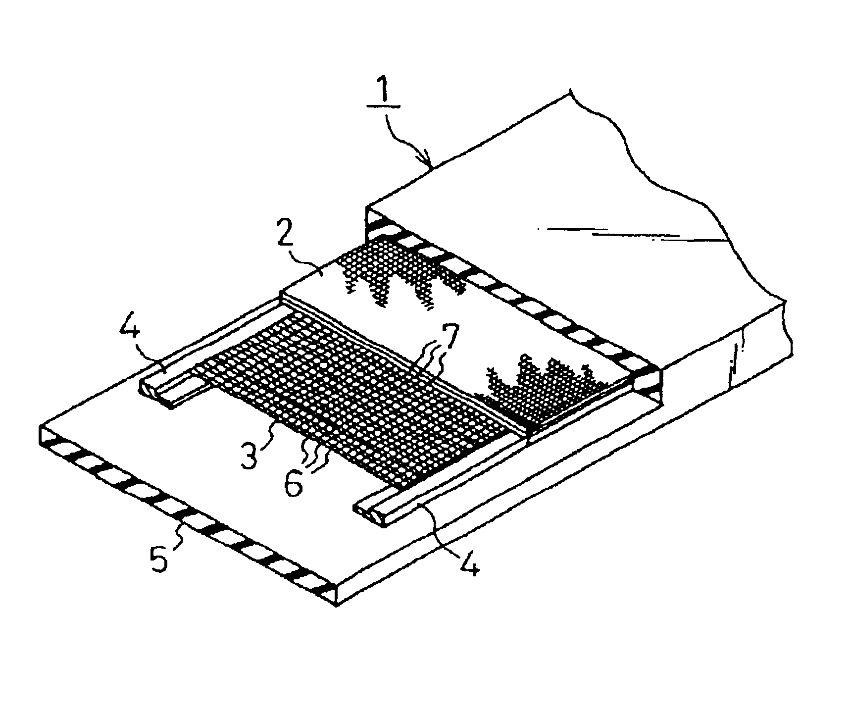
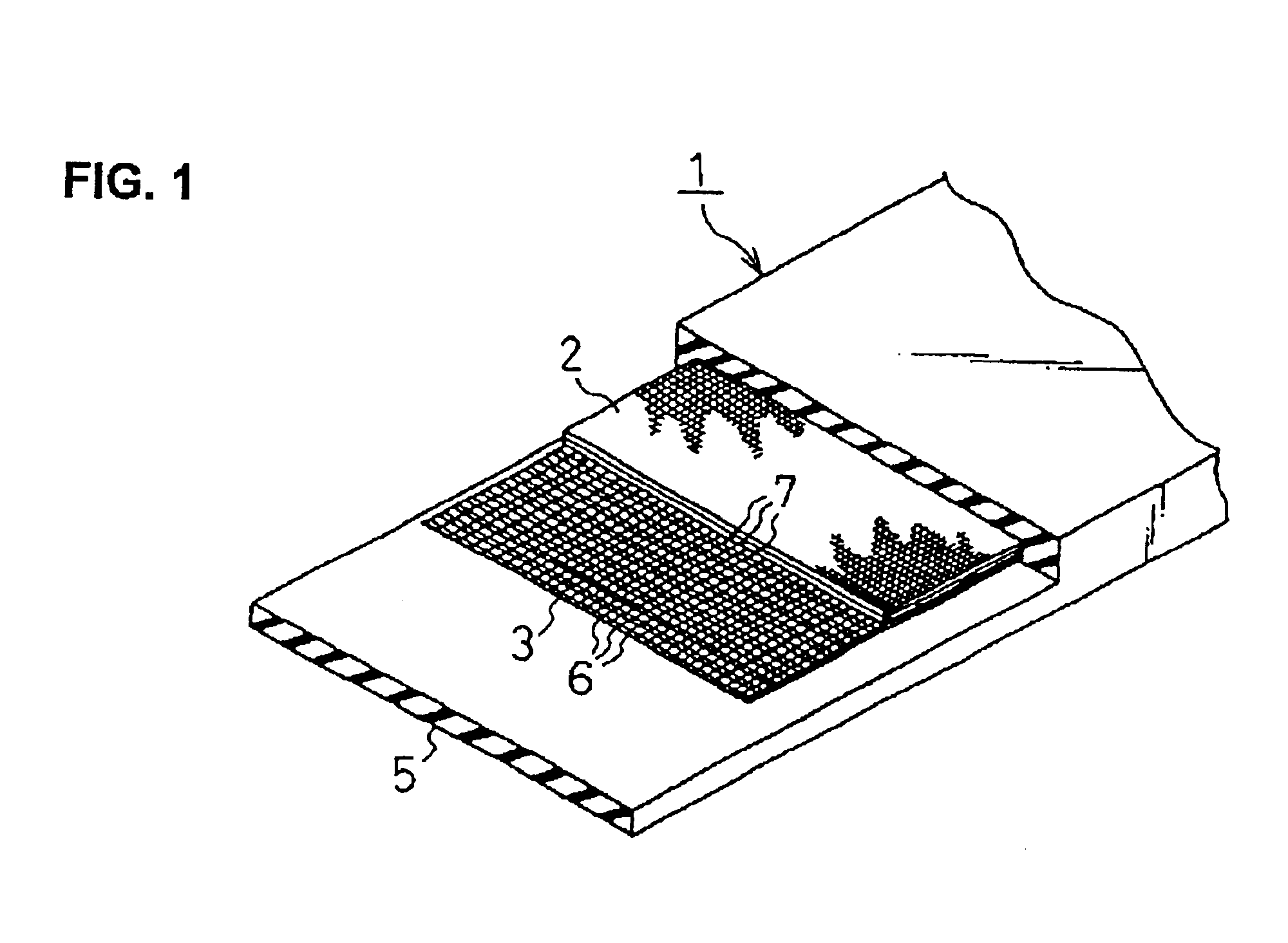
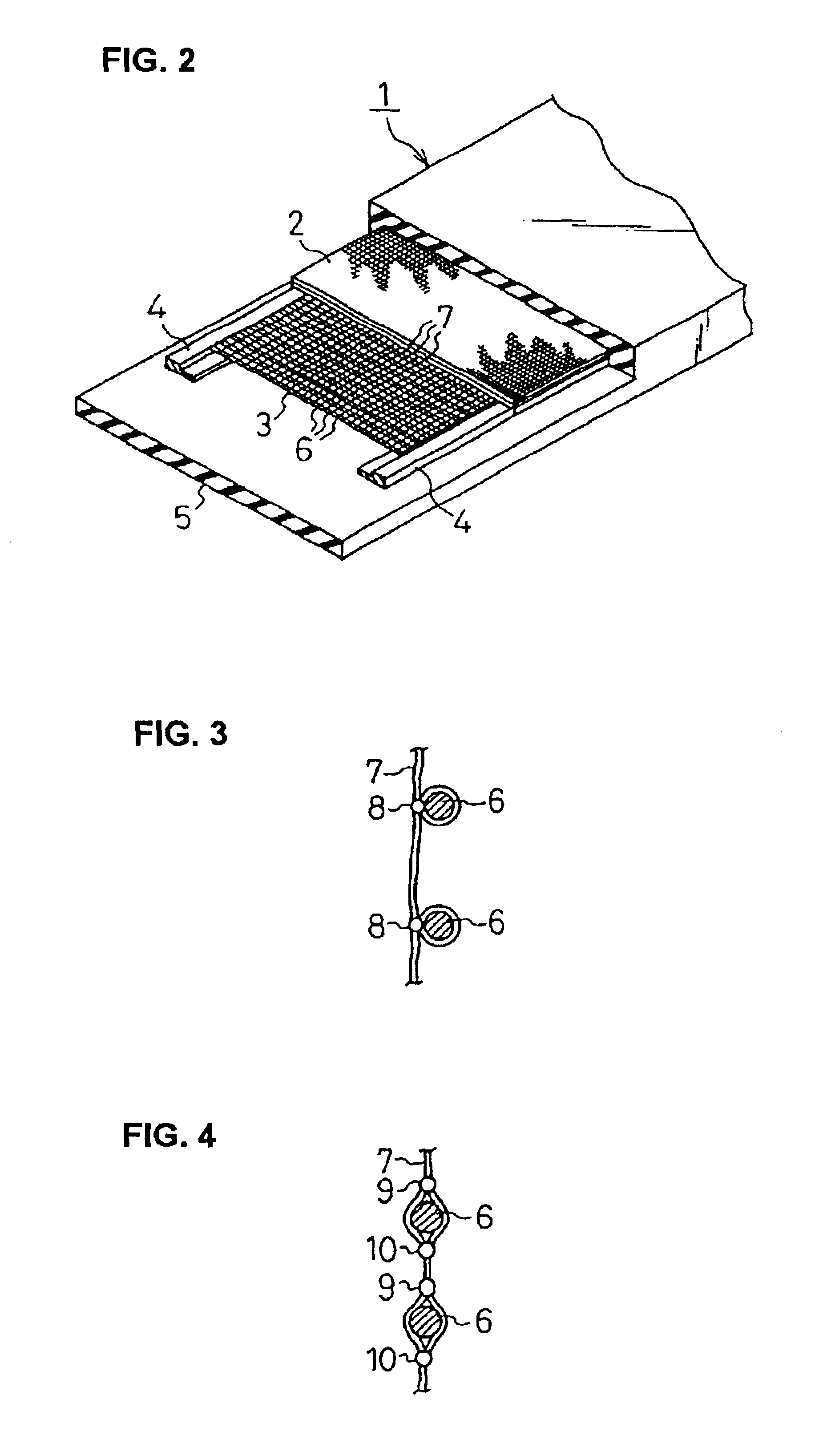
FIG. 1 is a partially cut-away perspective view of an embodiment of a conveyor belt according to the present invention, and FIG. 2 is a partially cut-away perspective view of an embodiment of a conveyor belt according to the present invention.

In belts 1,1′, on the lower surface of a core 2 in which a plurality of canvases are laminated, a slightly narrower reinforcing band 3 is overlapped. In a tubular belt conveyor in FIG. 2, the reinforcing band 3 is supported by a pair of thickness-adjusting breakers 4, and these elements are surrounded by a rubber layer 5.

In the reinforcing band 3, a plurality of rigid cords 6 spaced from each other are provided transversely with respect to a longitudinal direction of the belts 1,1′, and a plurality of warps are woven with the rigid cords 5 so that the warps are not to move longitudinally.

The rigid cords 6 may be made of synthetic fibers, aram...


PUM


Abstract

A durable reinforcing band for conveyer belts wherein a reinforcing band (3) is formed by interweaving a number of hard cords (6) facing a direction orthogonal to the longitudinal direction and longitudinally spaced at predetermined intervals with a number of longitudinally directed warp yarns (7) in such a manner as to prevent longitudinal shift, the reinforcing band (3) being disposed on the upper or lower surface of a core (2) composed of canvas or the like and being then surrounded by rubber (5), thereby forming a belt (1), and wherein the transverse stiffness and shape retainability of the belt can be enhanced by arranging the hard cords in a direction orthogonal to the longitudinal direction of the belt, and moreover, the hard cords are prevented from shifting longitudinally of the belt; and a conveyer belt, particularly pipe conveyer belt, using the same.

Description

BACKGROUND OF THE ARTThe present invention relates to a reinforcing band for conveyor belts and a conveyor belt using the same.In a tubular belt conveyor in which an endless flat belt is partially wound to form a tube in which loads are put and conveyed, long use decreases the quality of the belt to break the tubular form and cause twisting so as to open a closed portion, so that loads are likely to escape therefrom.To prevent such accident, a known conveyor belt, especially a tubular conveyor belt, includes various cores and reinforcing bands.Canvases are generally used as cores or reinforcing bands in such a known belt. In a known canvas, a weft is meandered to provide lateral elasticity, so that it is likely to deviate in a direction perpendicular to a running direction of the belt when the belt is used, thereby decreasing lateral rigidity of the belt to involve decrease in shape maintenance function.It is suggested that rigid cords such as wires are embedded longitudinally of a ...

Claims


Application Information

Patent Timeline
IPC IPC(8): B65G15/36B65G15/32
CPCB65G15/36B65G15/40B65G2201/06
Inventor NISHIKITA, YUKINOBU
Owner BRIDGESTONE CORP
Learn More