Progressive power lens

a technology of progressive power and lens, applied in the field of progressive power lens, can solve the problem of increasing the cost of progressive power lens

Inactive Publication Date: 2005-01-04
ASAHI KOGAKU KOGYO KK
View PDF8 Cites 7 Cited by
  • Summary
  • Abstract
  • Description
  • Claims
  • Application Information

AI Technical Summary

Benefits of technology

The present invention is advantageous in that a method is provided that prints a pattern, on a progressive power lens, including a mark which ap...

Problems solved by technology

Accordingly, the printing pattern 120 has to be redesigned for each progressive power lens ha...

Method used


Image

  • Progressive power lens
  • Progressive power lens
  • Progressive power lens

Examples


Embodiment Construction

Hereinafter, an embodiment of the present invention will be described with reference to the accompanying drawings.

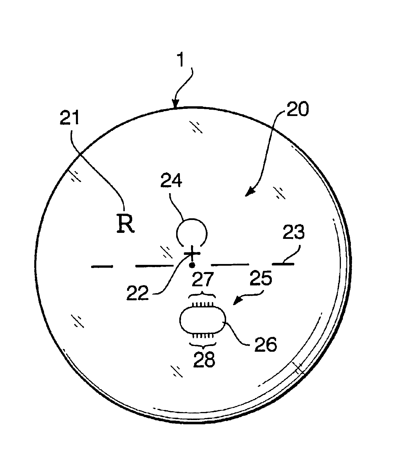
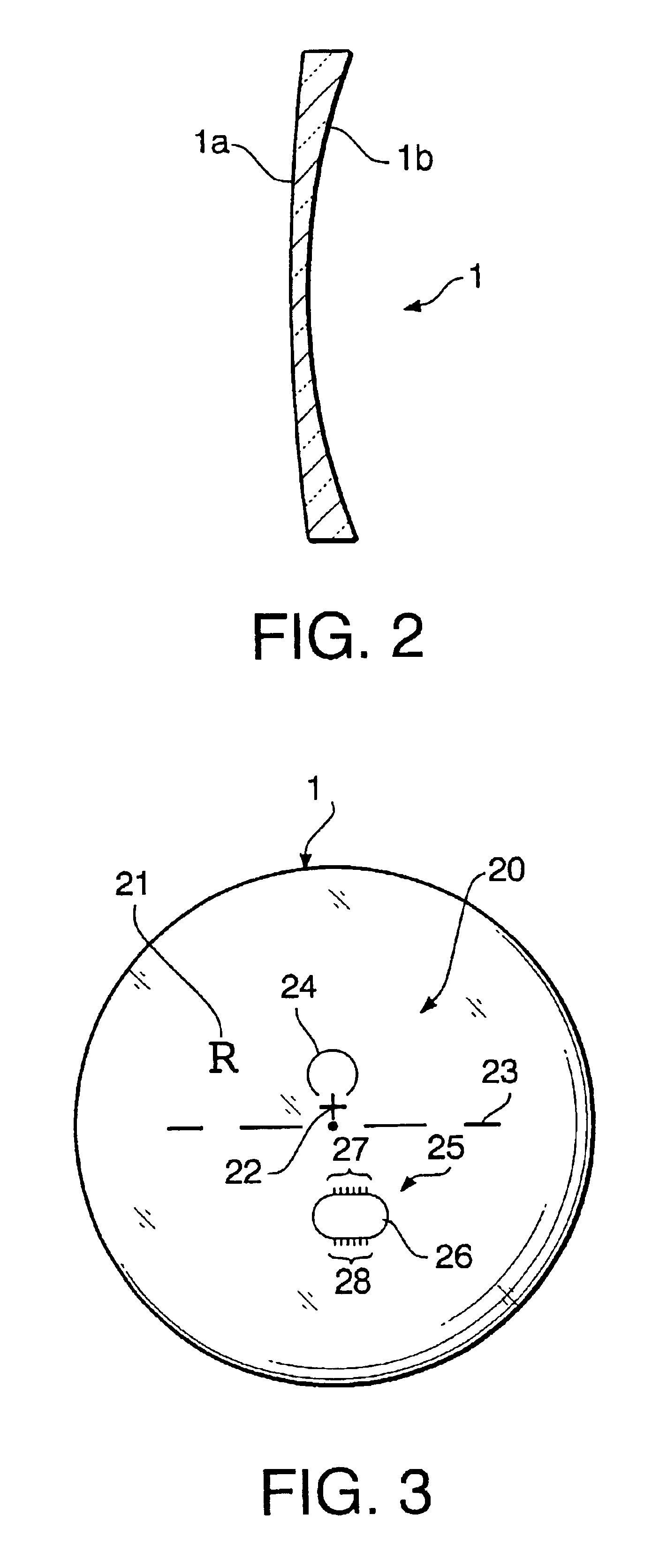
FIG. 2 is a sectional view of a progressive power lens 1 to which an embodiment according to the invention is applied, and, FIGS. 3 and 4 are, respectively, front and back views of the progressive power lens 1 shown in FIG. 2. Note that left- and right-hand sides in FIG. 2 correspond to a front side (an object side) and a back side of the progressive power lens 1, respectively.

The progressive power lens 1 shown in FIGS. 2 through 4 has a convex front surface 1a and a concave back surface 1b which is a progressive power surface. The back surface 1b or progressive power surface is provided with a printing pattern 20 which includes a left / right identification mark 21, a cross 22 for indicating the fitting point position, alignment reference marks 23, and distance and near reference area marks 24 and 25. The printing pattern 20 is provided to the progressive power lens 1 suc...


PUM


Abstract

A progressive power lens includes a convex front surface and a concave back surface which is also a progressive power surface. A pattern including distance and near reference area marks is printed on the concave back surface. The near reference area mark includes a closed curve and a scale arranged outside the closed curve. The closed curve is designed so as to enclose near reference areas of a plurality of progressive power lenses each having different dioptric power. The scale is designed so as to indicate the amount of inset of the progressive power lens.

Description

BACKGROUND OF THE INVENTIONThe present invention relates to a progressive power lens having a mark printed thereon that indicates the location for measuring the dioptric power thereof.FIG. 1A schematically shows typical structure of a conventional progressive power lens 100. The progressive power lens 100 typically has a distance portion 111 having a dioptric power for distance vision at an upper area thereof, a near portion 112 having a dioptric power for near vision at a lower area thereof, and an intermediate portion 113 between the distance portion 111 and the near portion 112. The dioptric power in the intermediate portion 113 progressively varies from the upper portion to the lower portion. Such variation in dioptric power is given by an asymmetrical shape formed on the front or back surface of the progressive power lens 100. The surface provided with the asymmetrical shape above is generally referred to as a progressive side surface.An imaginary line called main meridian 116 ...

Claims


Application Information

Patent Timeline
IPC IPC(8): G02C7/02
CPCG02C7/021G02C7/068G02C7/061
Inventor SENDA, YUKOTEJIMA, YASUYUKI
Owner ASAHI KOGAKU KOGYO KK
Why Eureka
Try Eureka