Brush holder for dynamoelectric machines

a technology of dynamoelectric machines and brushes, applied in the direction of current collectors, supports/encloses/casings, dynamo-electric machines, etc., can solve the problems of affecting the use of brushes, causing excessive friction and rapid brush wear, and reducing the use of brushes. , to achieve the effect of reducing contact force, reducing brush wear, and facilitating brush replacemen

Inactive Publication Date: 2005-01-04
SIEMENS ENERGY INC
View PDF4 Cites 11 Cited by
  • Summary
  • Abstract
  • Description
  • Claims
  • Application Information

AI Technical Summary

Benefits of technology

It is desired to provide a brush holder for a dynamoelectric machine that allows proper positioning of the brush relative to the commutator, easy brush replacement and minimal brush wear. The brush holder of the present invention comprises a first adjustable element for positioning the brush axially along the commutator and a second adjustable element for adjusting t

Problems solved by technology

Use of a relatively soft material causes the replaceable brush to wear, rather than the commutator.
The brush must not exert an undue force on the commutator, which would create excess friction and rapid brush wear.
However, an

Method used


Image

  • Brush holder for dynamoelectric machines
  • Brush holder for dynamoelectric machines
  • Brush holder for dynamoelectric machines

Examples


Embodiment Construction

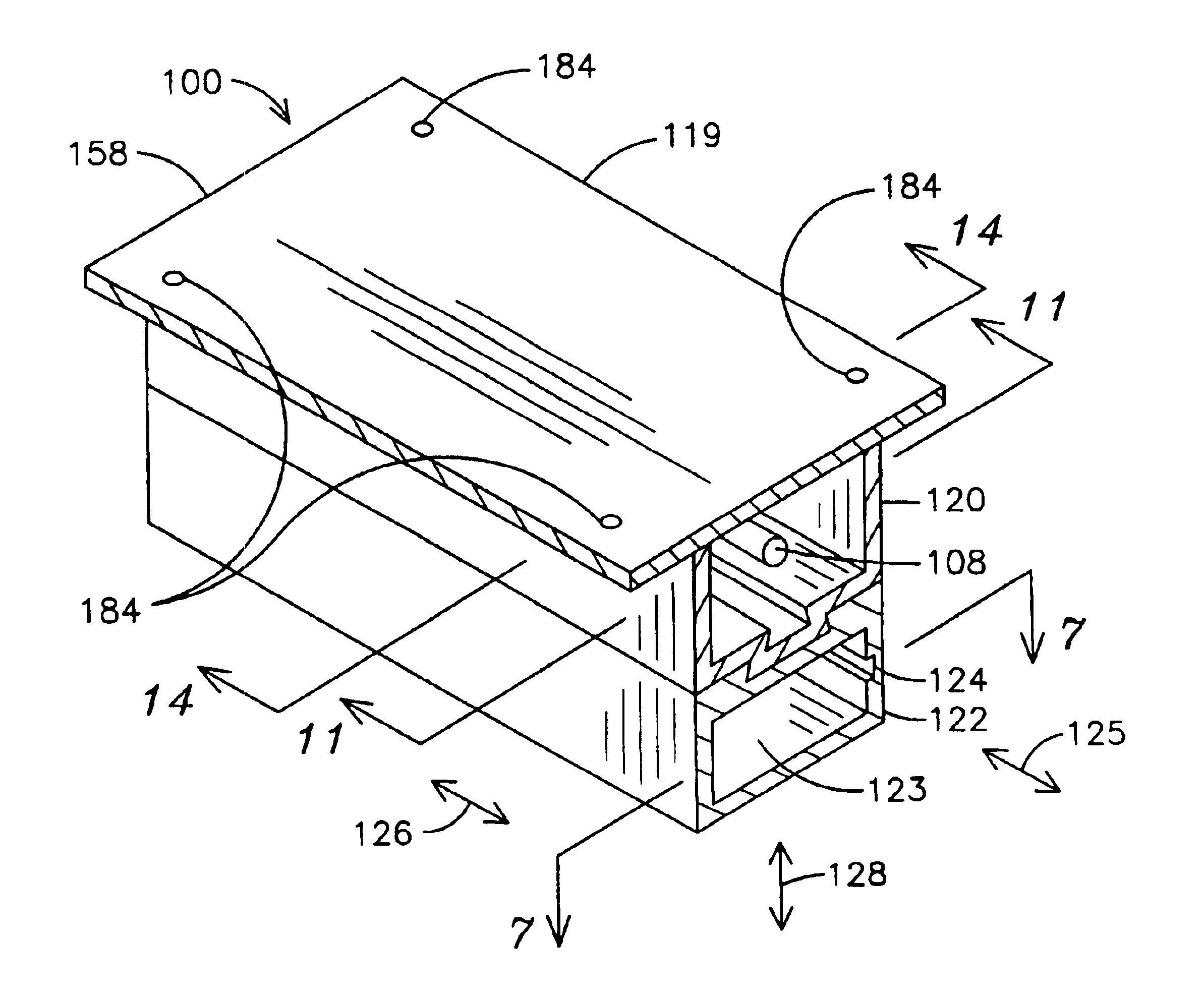
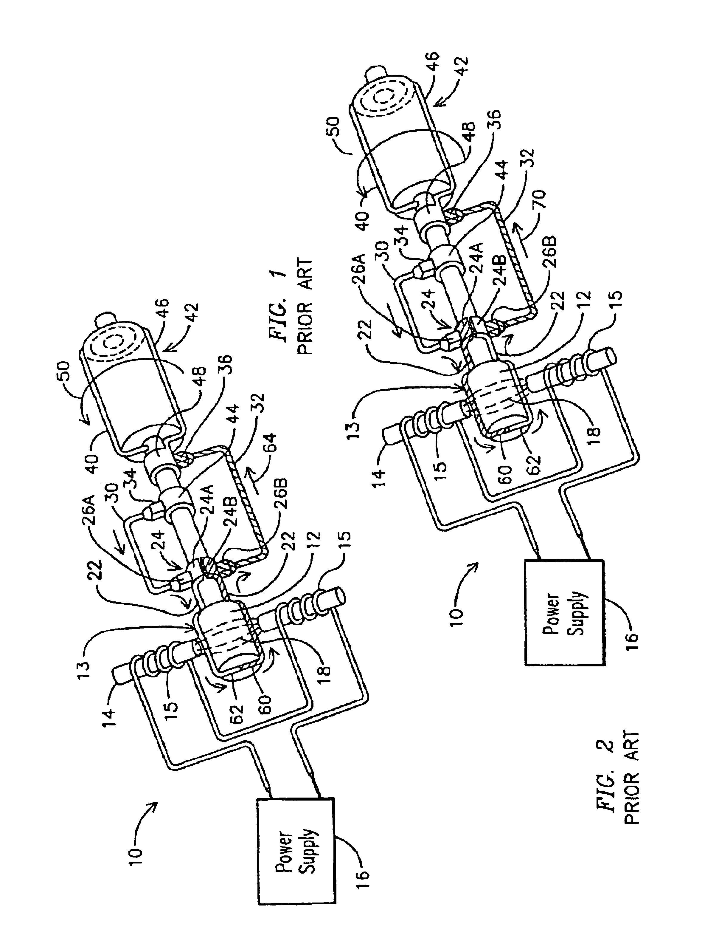
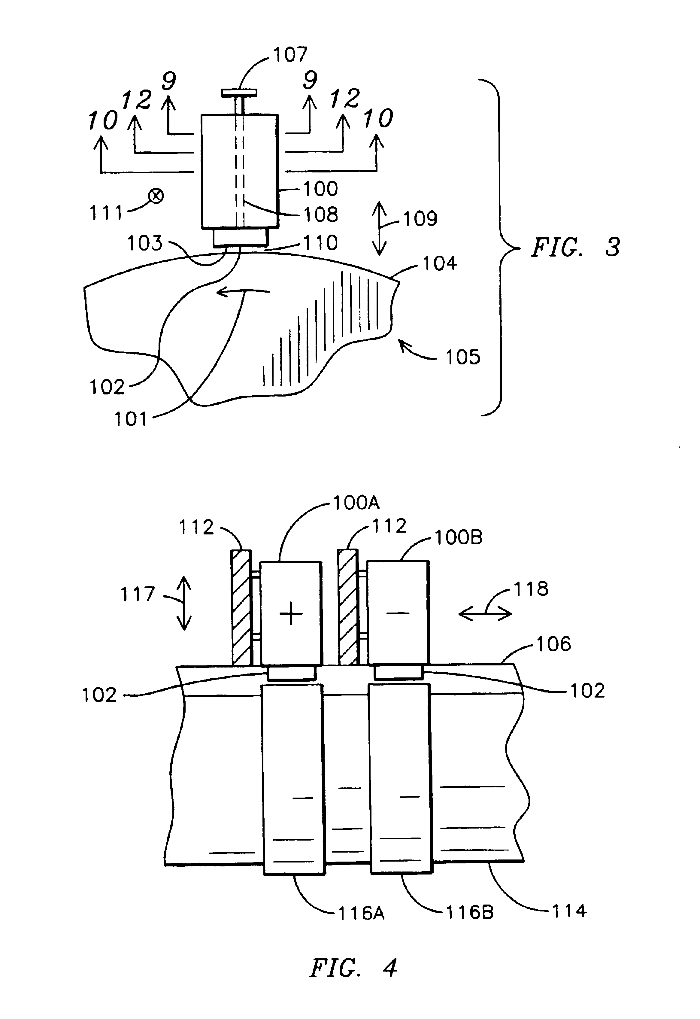
A brush holder 100 constructed according to the teachings of the present invention is illustrated generally in the axial view (i.e., along the axis of rotation 101 of the commutator) of FIG. 3. A brush 102 extends from the brush holder 100, such that a brush face 103 is proximate a commutator 104 (which functions in a similar manner to the commutator 24 of FIG. 1) of a dynamoelectric machine 105. The position of the brush 102 relative to the commutator 104 is adjustable by user operation of a handle 107, causing rotation of plurality of cams (not shown in FIG. 3) carried on a cam shaft 108 for performing the aforementioned brush adjustments. Generally, these brush adjustments provide axial adjustment of the brush 102 parallel to the axis of rotation of the commutator 104 and gap adjustment, i.e., adjusting the distance between the brush face 103 and the commutator 104.

The brush holder 100 provides for adjustment of a gap distance 110 to optimize current flow and brush life. Arrowhea...


PUM


Abstract

A brush holder (100) for carrying a brush (102) and for providing adjustment of the brush relative to the commutator (104) of a dynamoelectric machine (105). The brush holder provides for adjustment of the gap (110) between the commutator and the brush, and for adjustment of the brush in the axial direction along the commutator. The brush holder also locks the brush at the desired position for operation in the dynamoelectric machine.

Description

FIELD OF THE INVENTIONThe present invention relates generally to a brush holder for use with a brush assembly for a dynamoelectric machine, and more specifically to an adjustable brush holder for providing adjustment of the brush orientation with respect to the commutator.BACKGROUND OF THE INVENTIONGenerator action is employed in an electrical generator to produce an electrical output current from one or more stator windings. Conventionally, a generator comprises at least one stator winding carried on a stator core and a rotor shaft carrying a rotating field winding. Current is supplied to the rotating field winding from an exciter, as described further below, for creating a magnetic flux field that rotates within the stator core. One end of the rotor shaft is drivingly coupled to a steam or gas driven turbine for providing rotational energy to the rotor shaft and thus to the rotating field winding. The opposing end of the rotor shaft is coupled to the exciter. The rotating magnetic...

Claims


Application Information

Patent Timeline
IPC IPC(8): H02K5/14H01R39/00H01R39/38H01R39/40
CPCH01R39/385H02K5/148H01R39/40
Inventor TEKAWADE, AVINASH M.
Owner SIEMENS ENERGY INC
Why Eureka
Try Eureka