Breakaway coupling with flapper valve

a flapper valve and coupling technology, applied in the field of breakaway couplings, can solve the problems of affecting the operation of the valve, the monetary loss of fluid from such a rupture is nominal, and the fill line is ruptured,

Active Publication Date: 2005-01-11
PARKER INTANGIBLES LLC
View PDF11 Cites 53 Cited by
  • Summary
  • Abstract
  • Description
  • Claims
  • Application Information

AI Technical Summary

Benefits of technology

A breakaway coupler is disclosed for coupling an upstream hose with a downstream hose to pass fluid therebetween when coupled and closing flow when uncoupled. An upstream housing is securable to the upstream hose. An upstream coupling member is secured to the upstream housing and has a flow passage for fluid communication with the upstream hose. A downstream housing is securable to the downstream hose. A downstream coupling member is secured to the downstream housing and has a flow passage for fluid communication with the downstream hose.

Problems solved by technology

Occasionally, the driver of the transport vehicle inadvertently pulls away from the stationary vessel prior to disconnecting the flexible flow line, and the absence of a separable connection may otherwise cause a rupture of the fill line.
The monetary loss of fluid from such a rupture is nominal compared to the danger of releasing toxic vapors.
The release of anhydrous ammonia may seriously injure the operator, causing blindness, skin burns, or loss of smell.
For other potentially dangerous fluids, such as propane and liquid petroleum gas, the release of the fluid may cause adverse environmental consequences to the filling station site or create a fire hazard.
The first and most significant problem with the PIONEER coupler is the flow restriction caused by the spring loaded poppets positioned in the flow stream.
When the anhydrous ammonia meets a restriction in the application system, a pressure drop occurs, decreasing the maximum deliverable flow rate of the system.
The difference can amount to additional days required to do the job.
A further problem with existing locking ball couplers is the difficulty of manually coupling or uncoupling them.
The manual application of that level of force to a flexibly mounted coupler is at best difficult and at worst dangerous to do.

Method used


Image

  • Breakaway coupling with flapper valve
  • Breakaway coupling with flapper valve
  • Breakaway coupling with flapper valve

Examples


Embodiment Construction

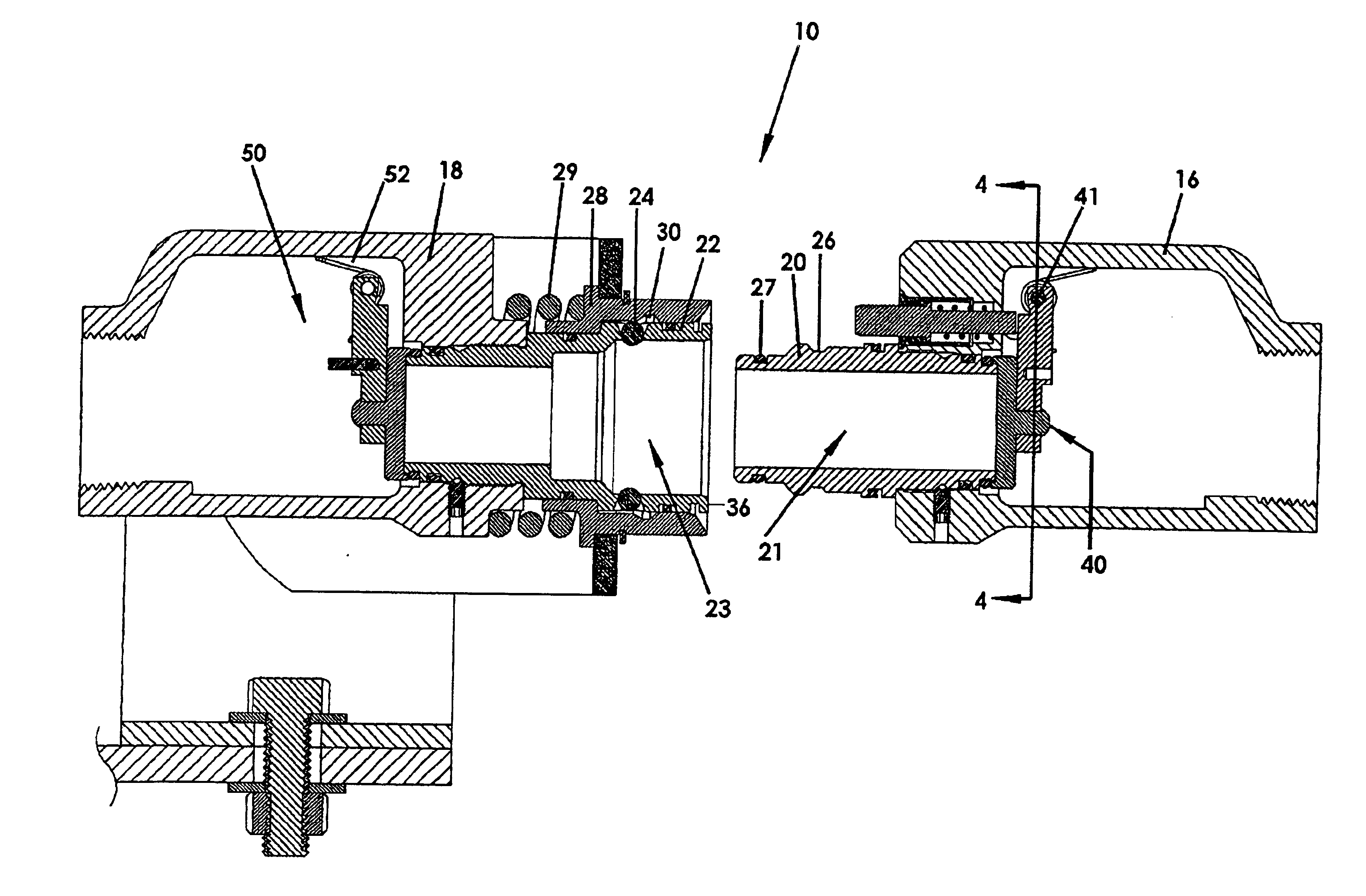
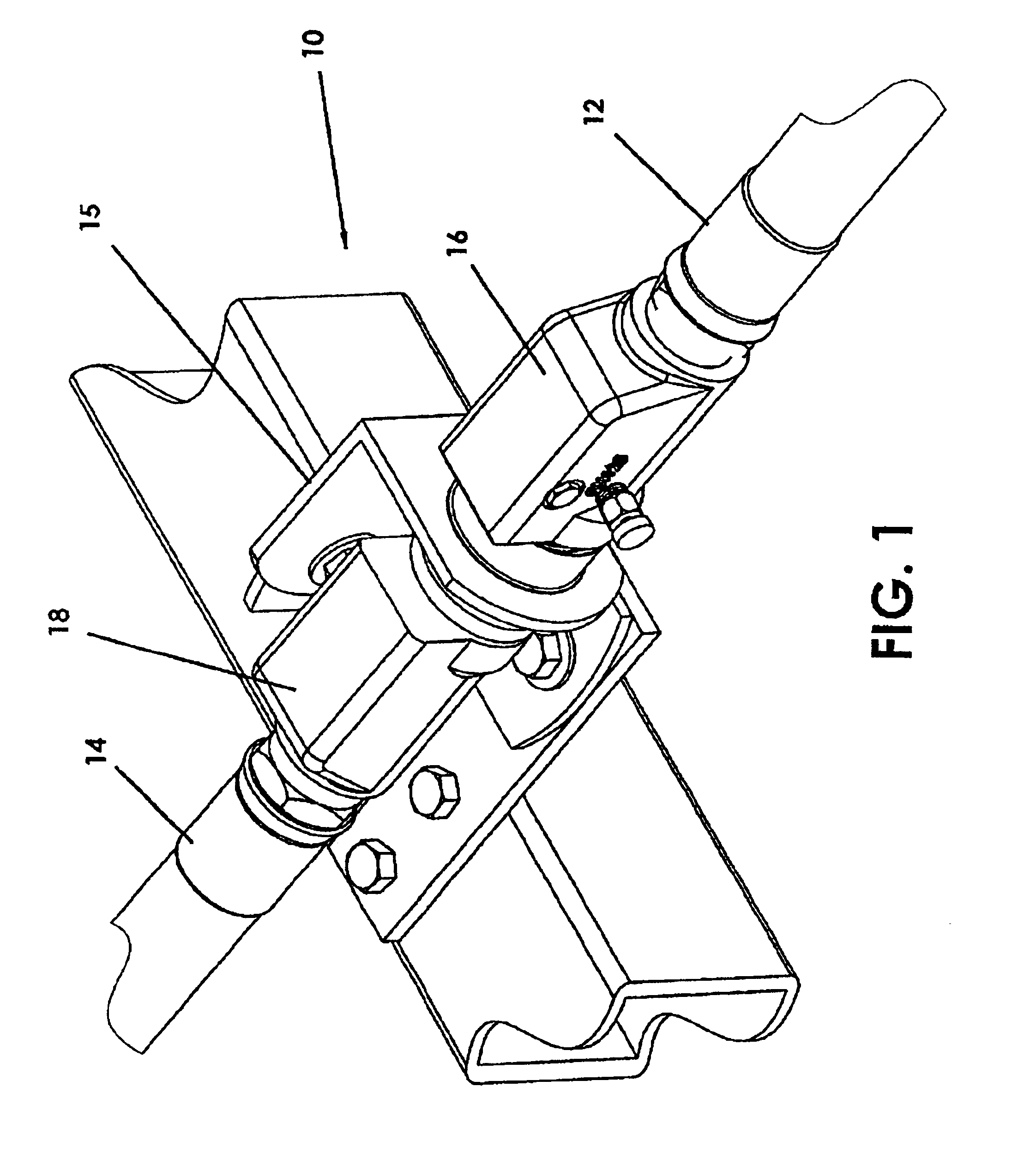
FIG. 1 shows a perspective view of a breakaway coupler 10 for coupling an upstream hose 12 with a downstream hose 14 for passing fluid therebetween when coupled and closing flow when uncoupled. An upstream housing 16 is secured to the upstream hose 12 and a downstream housing 18 is secured to the downstream hose 14. Bracket 15 may be used for mounting the breakaway coupler 10 to a suitable structural support. The upstream hose 12 typically supplies fluid from a portable nurse tank, and the downstream hose 14 may be connected to a fertilizer applicator on a moving farm vehicle.

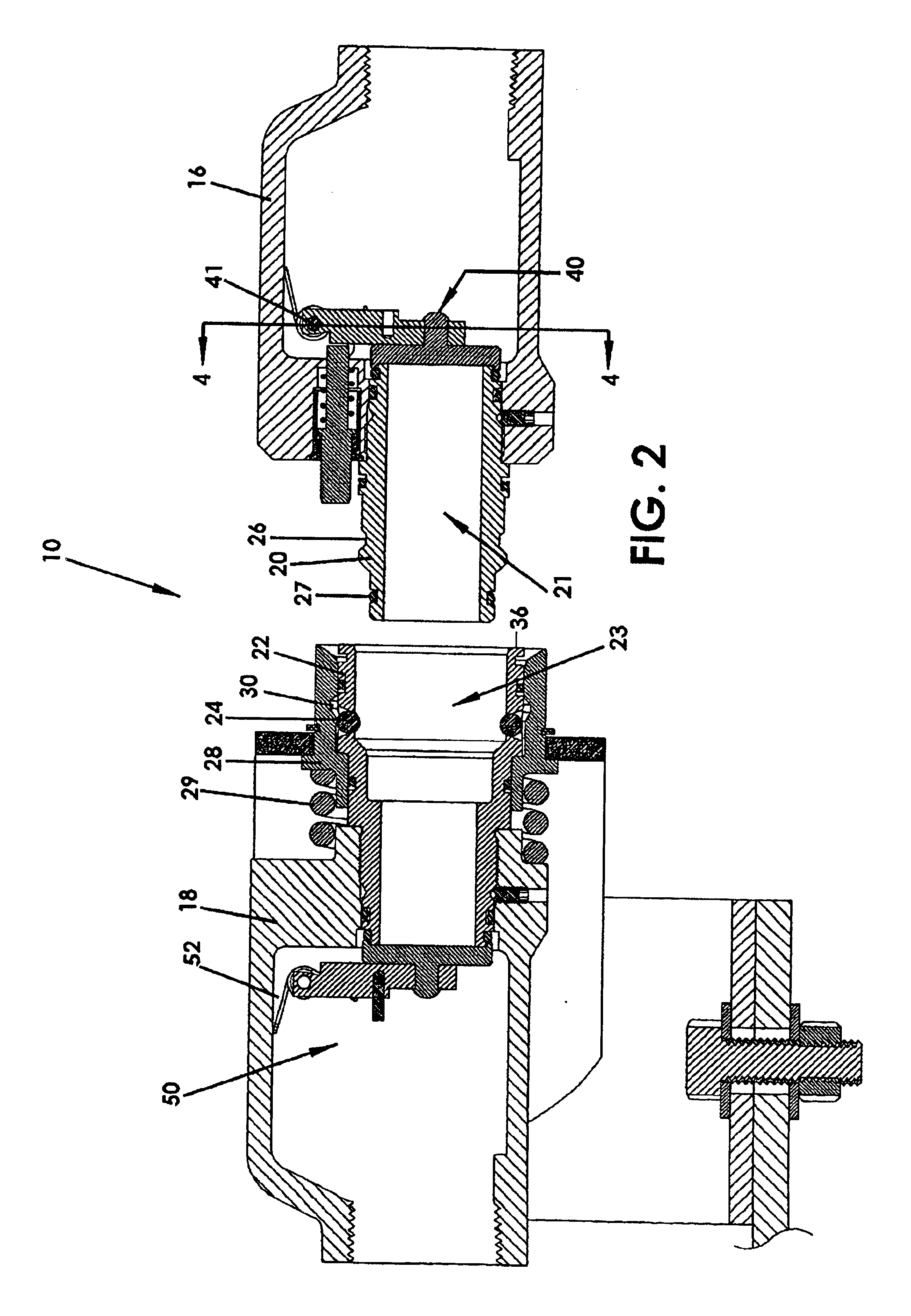
FIG. 2 shows a more detailed view of the breakaway coupler 10 when unlocked. An upstream coupling member 20 is secured to the upstream housing 16 and has a flow passage 21 for fluid communication with the upstream hose (not shown). A downstream coupling member 22 is threadedly secured to the downstream housing 18 and has a flow passage 23 for fluid communication with the downstream hose (not shown). A locking m...


PUM


Abstract

A breakaway coupler for coupling upstream and downstream hose includes one or more locking balls carried by a downstream coupling member. An upstream flapper is pivotally secured with respect to an upstream housing. A pushrod is axially movable in response to engagement by the downstream coupling member. A pry recess on the downstream coupling member is spaced between the downstream housing g and the upstream housing, such that a tool inserted into the pry recess is leverageable to move the downstream coupling member to unlock the breakaway coupler.

Description

FIELD OF THE INVENTIONThe invention relates to a breakaway coupling with improved reliability and reduced service costs. More particularly, this invention relates to a breakaway coupling particularly suitable for positioning between a liquid anhydrous-ammonia nurse tank and an applicator for applying the liquid anhydrous ammonia to the field. Upon separation, each coupling half is automatically sealed for retaining the liquid anhydrous ammonia in the flow lines extending to and from the coupling.BACKGROUND OF THE INVENTIONFlow line systems which transport potentially dangerous fluids, such as anhydrous ammonia, commonly include a separable connection for emergency interruption of the flow line which extends between a stationary vessel and a potentially portable vessel, such as a transport vehicle. Occasionally, the driver of the transport vehicle inadvertently pulls away from the stationary vessel prior to disconnecting the flexible flow line, and the absence of a separable connecti...

Claims


Application Information

Patent Timeline
Patent Type & Authority Patents(United States)
IPC IPC(8): F16L29/04F16L29/00F16L55/10
CPCF16L29/04F16L55/1018F16L55/1007Y10T137/1654Y10T137/87965
Inventor NIMBERGER, SPENCER M.
Owner PARKER INTANGIBLES LLC
Why Eureka
Try Eureka