Height adjustable arm assembly

a technology of adjustable arm and armrest, which is applied in the direction of stools, vehicle seats, seating furniture, etc., can solve the problems of not being able to meet the requirements of office chairs, not being able to adjust, and being difficult to repair,

Inactive Publication Date: 2005-01-11
FORMWAY FURNITURE
View PDF512 Cites 49 Cited by
  • Summary
  • Abstract
  • Description
  • Claims
  • Application Information

AI Technical Summary

Benefits of technology

The liner may include an aperture for receipt of the locking device, with the locking device extending inwardly through the aperture. The liner suitably includes a strengthened region adjacent the aperture for receipt of the locking device, to enhance the rigidity of the locking device.
The liner may include an outwardly-extending leaf spring to reduce slack between the liner and the outer stem. Additionally or alternatively, the liner may include an inwardly-extending leaf spring to reduce slack between the liner and in the inner stem.
A camming surface may define an edge of each recess of the release member towards the outer stem, such that movement of the release member away from the outer stem forces the locking device from the recess or recesses of the inner stem. Preferably, the release member is biased in a direction toward the outer stem. The actuator preferably includes a height adjustment lever extending through the inner stem at or adjacent an end thereof distal from the outer stem, which lever is in operable engagement with the release member. Preferably, the lever is slidably mounted in the inner stem such that moving the lever in a direction away from the outer stem moves the release member in a direction away from the outer stem and thereby forces the locking device from the recess or recesses of the inner stem, enabling the relative positions of the inner and outer stems to be adjusted.
Alternatively, a camming surface may define an edge of each recess of the release member away from the outer stem, such that movement of the release member towards the outer stem forces the locking device from the recess or recesses of the inner stem. Preferably, the release member is biased in a direction away from the inner stem. The actuator preferably includes a height adjustment lever extending through the inner stem at or adjacent an end thereof distal from the outer stem, which lever is in operable engagement with the release member. Preferably, the lever is pivotally mounted to the inner stem such that moving an outer part of the lever in a direction away from the outer stem moves the release member toward the outer stem and thereby forces the locking device from the recess or recesses of the inner stem, enabling the relative positions of the inner and outer stems to be adjusted.
A camming surface may define an edge of each recess of the release member towards the outer stem, such that movement of the release member away from the outer stem forces the locking device from the recess or recesses of the inner stem. Preferably, the release member is biased in a direction toward the outer stem. The actuator preferably includes a height adjustment lever extending through the outer stem at or adjacent an end thereof distal from the inner stem, which lever is in operable engagement with the release member. Preferably, the lever is pivotally mounted to the outer stem such that moving an outer part of the lever away from the inner stem moves the release member away from the outer stem and thereby forces the locking device from the recess or recesses of the inner stem, enabling the relative positions of the inner and outer stems to be adjusted
Alternatively, a camming surface may define an edge of each recess of the release member away from the outer stem, such that movement of the release member towards the outer stem forces the locking device from the recess or recesses of the inner stem. Preferably, the release member is biased in a direction away from the inner stem. The actuator preferably includes a height adjustment lever extending through the inner stem at or adjacent an end thereof distal from the inner stem, which lever is in operable engagement with the release member. Preferably, the lever is slidably mounted to the outer stem such that moving the lever in a direction away from the inner stem moves the release member toward the outer stem and thereby forces the locking device from the recess or recesses of the inner stem, enabling the relative positions of the inner and outer stems to be adjusted.

Problems solved by technology

As the occupant adjusts their seat depth, the positioning of the armrests relative to the seat will vary even to the extent that the positioning of the armrests may be totally inappropriate for the occupant.
Known office chairs do not satisfactorily meet the requirement of being easily adjustable to accommodate the seat depth position.
Another shortcoming of known armrest adjustment mechanisms is that they are not easy to adjust.
Further, many of them have a large number of moving parts, meaning they can be expensive to manufacture and difficult to repair.
However, if the user unintentionally bears considerable force against the armrests they can move.
This can be destabilising to the occupant and moreover, requires the occupant to re-adjust the armrests when he resumes occupancy of the chair.

Method used


Image

  • Height adjustable arm assembly
  • Height adjustable arm assembly
  • Height adjustable arm assembly

Examples


Embodiment Construction

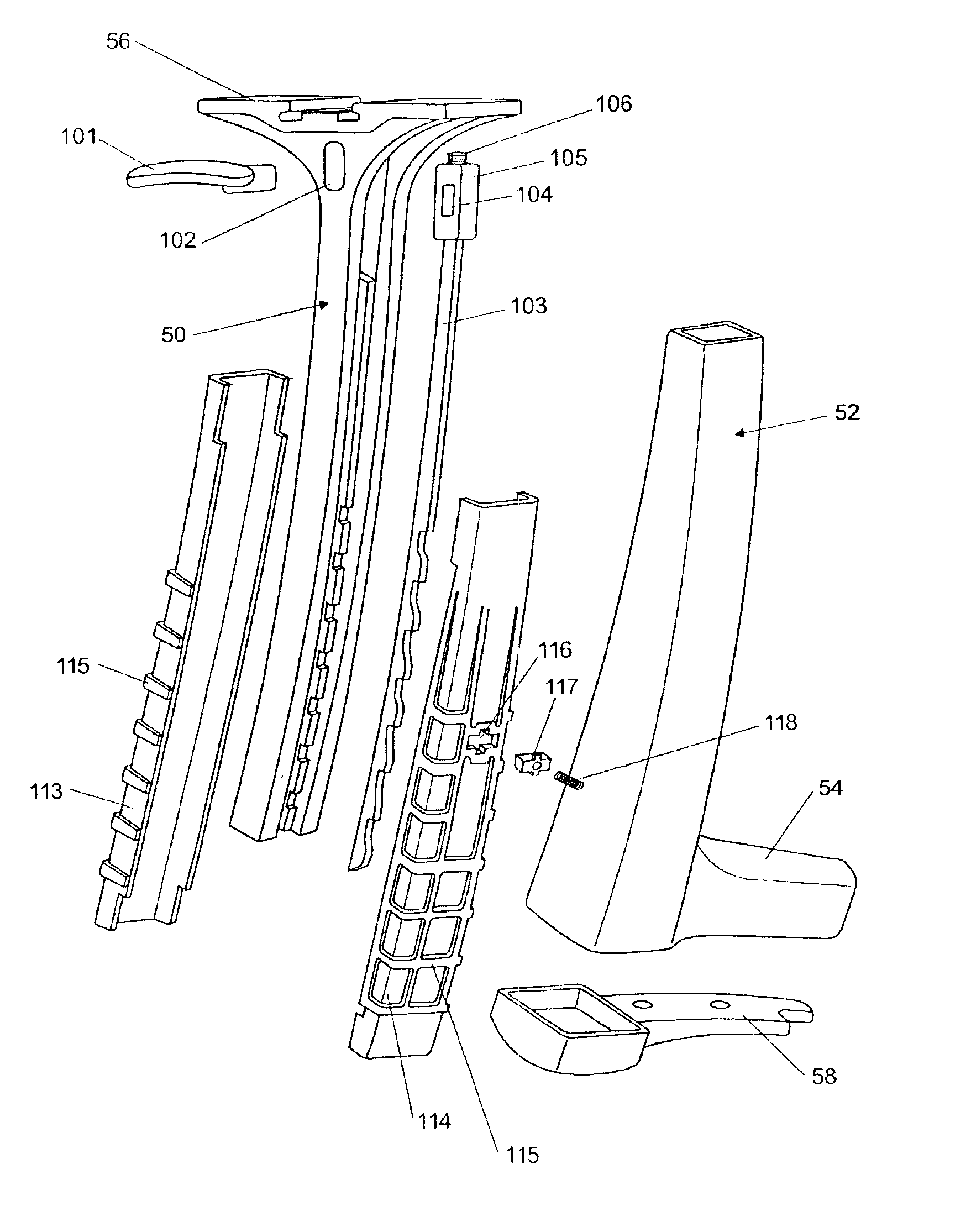
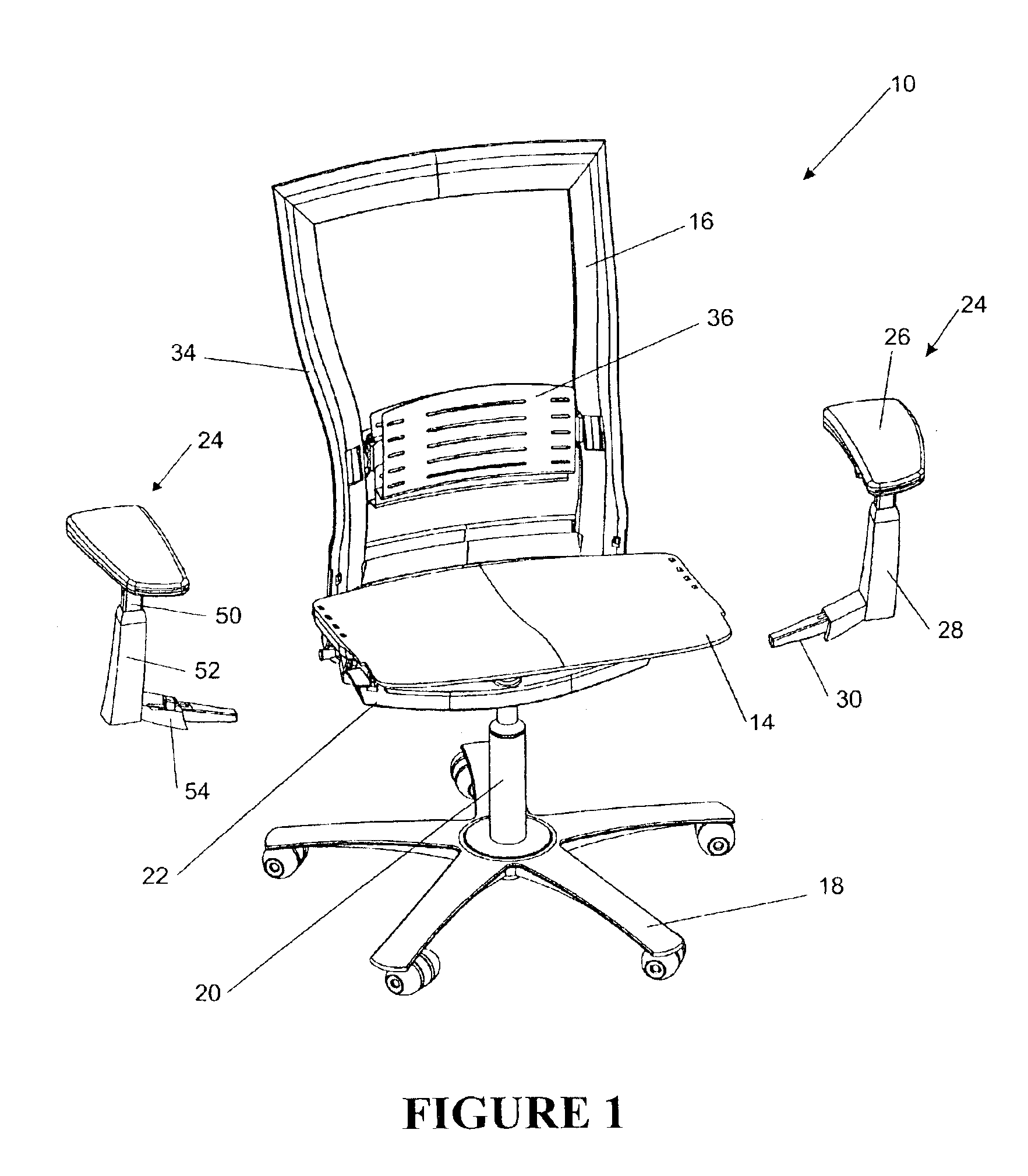
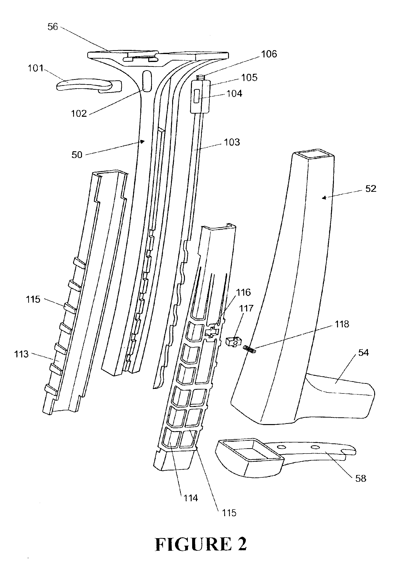
FIG. 1 illustrates an office chair including a main assembly 10 having a seat portion 14 and a back portion 16. The seat portion 14 and the back portion 16 are supported above the ground by a support frame including a wheeled base 18 and a central support column 20. The support frame may also optionally include a mechanism enabling the back portion 16 to recline with a synchronous tilting action of the seat portion 14 as the back portion 16 reclines. The details of the mechanism are not important to the present invention and the reader may refer to our co-pending patent application U.S. Ser. No. 09 / 953,816, the details of which are incorporated by reference herein. The central support column 20 may house a pneumatic spring (not shown) for height adjustment of the seat portion 14 in conventional fashion. The pneumatic spring is connected to the main transom 22 of the chair, which extends transversely across the chair and is connected to the pneumatic spring by way of central spring c...


PUM


Abstract

An arm assembly includes an outer stem (52) and an inner stem (50) slidable in the outer stem and including a number of recesses (107) along its length. A biased locking device (117) engages one or more of the recesses (107) to lock the position of the inner stem (50) relative to the outer stem (52). A release member (103) operably connected to an actuator (101) has a number of recesses (110) and raised surfaces (112), the release member (103) slidable relative to the inner stem (50) between a first position in which recess(es) (110) in the release member is / are aligned with recess(es) (107) of the inner stem and the locking device (117) engages recess(es) in the stem (50) to inhibit movement thereof relative to the outer stem, and a second position in which raised surface(s) (112) of the release member align(s) with recess(es) (107) of the stem (50) to disengage the locking device from the recess(es) of the stem.

Description

FIELD OF THE INVENTIONThe present relation relates to an arm assembly. In particular, although not exclusively, the invention relates to an arm assembly for supporting an armrest from an office chair where the height of the armrest is adjustable for the comfort of the occupant. While the invention is described herein in terms of an office chair, it will be understood that the invention can be implemented in any type of chair including a wheelchair. Moreover, the invention might also have application beyond chairs. Arm assemblies of the invention may be attachable to a table or workstation, for example to be used as typists' aids.BACKGROUND TO THE INVENTIONHuman beings come in all different shapes and sizes. For this reason, office chairs generally allow for adjustment eg seat height, seat depth. It is also known to provide for adjustment of armrests. A known adjustment includes a twisting action about a vertical axis. Another known type permits a twisting action as well as sideways ...

Claims


Application Information

Patent Timeline
Patent Type & Authority Patents(United States)
IPC IPC(8): A47C7/36A47C7/38A47C1/03A47C1/022
CPCA47C7/38A47C1/03
Inventor BURWELL, DAMON GREGORYWILKINSON, PAUL MICHAEL
Owner FORMWAY FURNITURE
Why Eureka
Try Eureka