Ink jet recording apparatus

a recording apparatus and jet technology, applied in the direction of typewriters, printing apparatus, printing, etc., can solve the problems of air bubbles in the nozzle, the vibration of the meniscus becomes so intense and disturbing, and the difficulty in reducing the volume of each discharged ink drop, so as to minimize the possibility of ink in the nozzl

Inactive Publication Date: 2005-01-11
TOSHIBA TEC KK
View PDF32 Cites 20 Cited by
  • Summary
  • Abstract
  • Description
  • Claims
  • Application Information

AI Technical Summary

Benefits of technology

The object of the present invention is to provide an ink jet recording apparatus capable of minimizing the possibility of ink in nozzles involving air bubbles even when gradational printing is carried out in a manner such that a plurality of ink droplets are continuously discharged to change the dot size.

Problems solved by technology

In the case of the former gradational printing, it is hard considerably to change the volume of each discharged ink drop.
Accordingly, the vibration of the meniscuses becomes so intensive and disturbing that ink in the nozzles involves air bubbles.

Method used


Image

  • Ink jet recording apparatus
  • Ink jet recording apparatus
  • Ink jet recording apparatus

Examples


Embodiment Construction

An embodiment of the present invention will now be described with reference to the accompanying drawings.

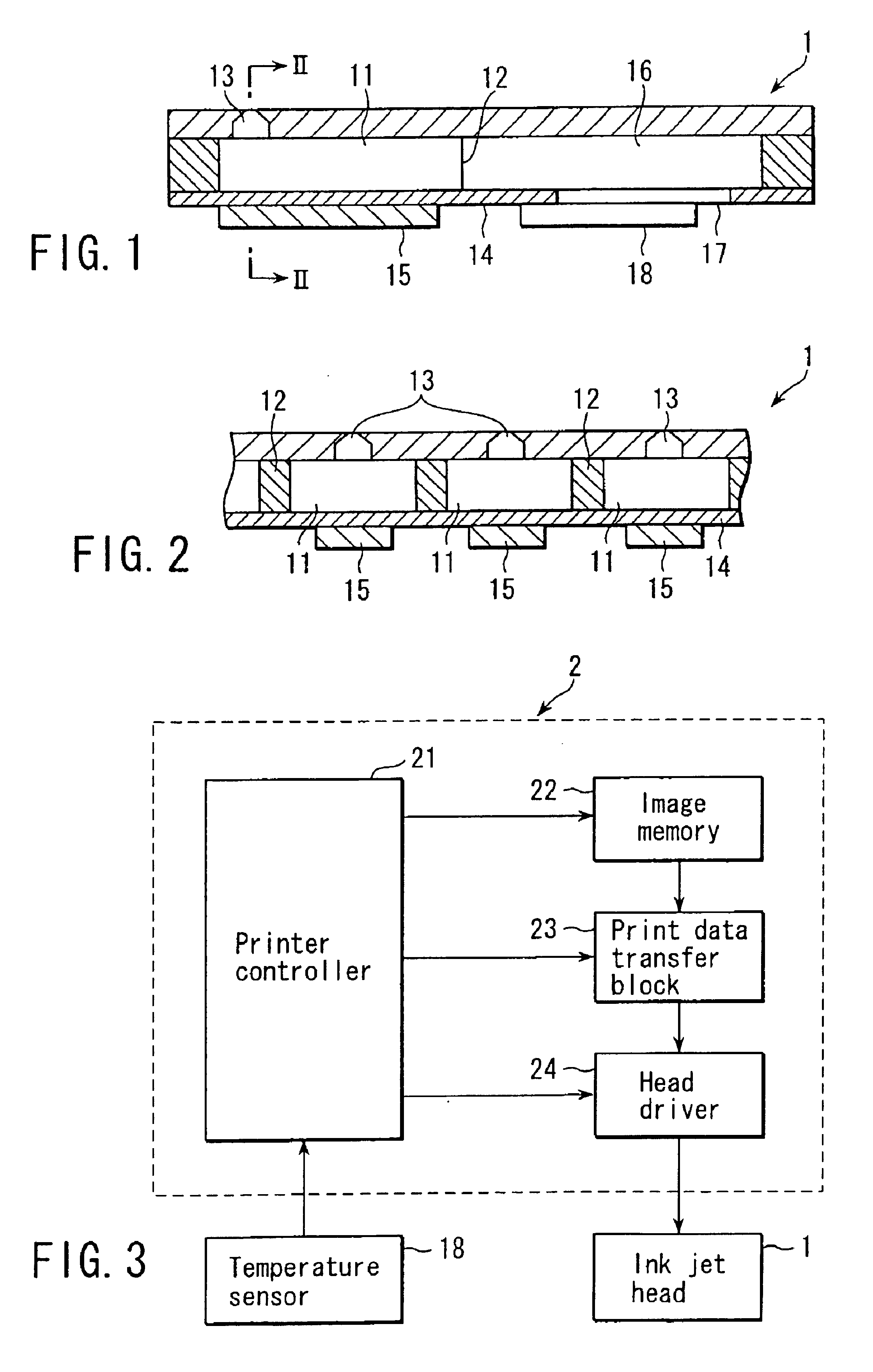
FIGS. 1 and 2 are views showing the configuration of the principal mechanism of an ink jet recording apparatus. In these drawings, numeral 1 denotes an ink jet head 1. FIG. 2 is a sectional view taken along line II—II of FIG. 1.

The ink jet head 1 is formed by dividing a plurality of pressure chambers 11 for ink storage by means of partition walls 12. Each pressure chamber 11 is provided with a nozzle 13 for discharging ink drops. The base of each pressure chamber 11 is formed of a vibration plate 14. A piezoelectric member 15 is fixed on the base side of the vibration plate 14 corresponding to each pressure chamber 11. The vibration plate 14 and the piezoelectric member 15 constitute an actuator.

The ink jet head 1 is formed having a common pressure chamber 16 that communicates with each pressure chamber 11. Ink is injected from an ink supply unit (not shown) into the chamber 16 t...


PUM


Abstract

An ink jet recording apparatus according to the present invention includes a pressure chamber stored with ink, a nozzle communicating with the pressure chamber and capable of discharging the ink from the pressure chamber, and an actuator for increasing and reducing the capacity of the pressure chamber in response to driving signals from a driving signal generator. The driving signal generator successively generate, an expansion pulse for increasing the capacity of the pressure chamber and a contraction pulse for reducing the capacity of the pressure chamber with a timing such that a time lag between the respective centers of the expansion pulse and the contraction pulse matches the resonance period of a meniscus generated in the nozzle by the ink in the pressure chamber. Thus, the ink jet recording apparatus continuously discharges a plurality of ink drops through the nozzle to form a pixel.

Description

CROSS-REFERENCE TO RELATED APPLICATIONSThis application is based upon and claims the benefit of priority from the prior Japanese Patent Application No. 2001-191800, filed Jun. 25, 2001, the entire contents of which are incorporated herein by reference.BACKGROUND OF THE INVENTION1. Field of the InventionThe present invention relates to an ink jet recording apparatus for gradational printing such that a plurality of ink drops are continuously discharged through nozzles.2. Description of the Related ArtConventionally known is an ink jet recording apparatus in which an actuator composed of an electromechanical transducer such as a piezoelectric element is operated by means of driving signals to increase or reduce the capacity of a pressure chamber that is stored with ink, whereby the ink is discharge through nozzles to print a pixel by gradation. Ink jet recording apparatuses of this type are described in Jpn. Pat. Appln. KOKAI Publication No. 4-250045 and U.S. Pat. No. 4,513,299, for e...

Claims


Application Information

Patent Timeline
Patent Type & Authority Patents(United States)
IPC IPC(8): B41J2/045B41J2/055B41J2/205
CPCB41J2/04581B41J2/04595B41J2/04588
Inventor KUSUNOKI, RYUTARO
Owner TOSHIBA TEC KK
Why Eureka
Try Eureka