Graytone mask and manufacturing method thereof

a technology of graytone and mask, which is applied in the field of graytone mask, can solve the problems of inability to achieve the desired geometrical and dimensional accuracy of a desired pattern, minute opaque pattern posed an obstacle to commercialization, geometrical and dimensional accuracy,

Inactive Publication Date: 2005-01-11
HOYA CORP
View PDF2 Cites 19 Cited by
  • Summary
  • Abstract
  • Description
  • Claims
  • Application Information

AI Technical Summary

Benefits of technology

[0018]a graytone part which is an area wherein there is formed an opaque pattern of not exceeding the resolution limit of an exposure apparatus using the mask and which reduces the amount of exposing radiation transmitted through the area, wherein
[0025]a graytone part which is an area wherein there is formed an opaque pattern of not exceeding the resolution limit of an exposure apparatus using the mask and which reduces the amount of exposing radiation transmitted through the area, wherein
[0032]a graytone part which is an area wherein there is formed an opaque pattern of not exceeding the resolution limit of an exposure apparatus using the mask and which reduces the amount of exposing radiation transmitted through the area, wherein
[0039]a graytone part which is an area wherein there is formed an opaque pattern of not exceeding the resolution limit of an exposure apparatus using the mask and which reduces the amount of exposing radiation transmitted through the area, wherein
[0044]a graytone part which is an area wherein there is formed an opaque pattern of not exceeding the resolution limit of an exposure apparatus using the mask and which reduces the amount of exposing radiation transmitted through the area, wherein, an opaque pattern is formed in a graytone part adjacent to the opaque part and / or the transmission part so as to improve the geometrical and dimensional accuracy of a resist pattern located in a boundary part between the graytone part and the opaque part and / or the transmission part and, to improve evenness of thickness of a resist in the entire area of graytone part, when a resist pattern is transferred onto a resist film on a target substrate through use of a graytone mask.

Problems solved by technology

As a result, the geometrical and dimensional accuracy of a resist pattern corresponding to the main pattern is deteriorated, thereby resulting in a failure to achieve a desired geometrical and dimensional accuracy of a desired pattern.
Thus, the minute opaque pattern has posed an obstacle to commercialization.
The resist patterns 11, 11′ are deteriorated in geometrical and dimensional accuracy, thus posing an obstacle to commercialization of a pattern transfer process using a graytone mask.

Method used


Image

  • Graytone mask and manufacturing method thereof
  • Graytone mask and manufacturing method thereof
  • Graytone mask and manufacturing method thereof

Examples


third embodiment

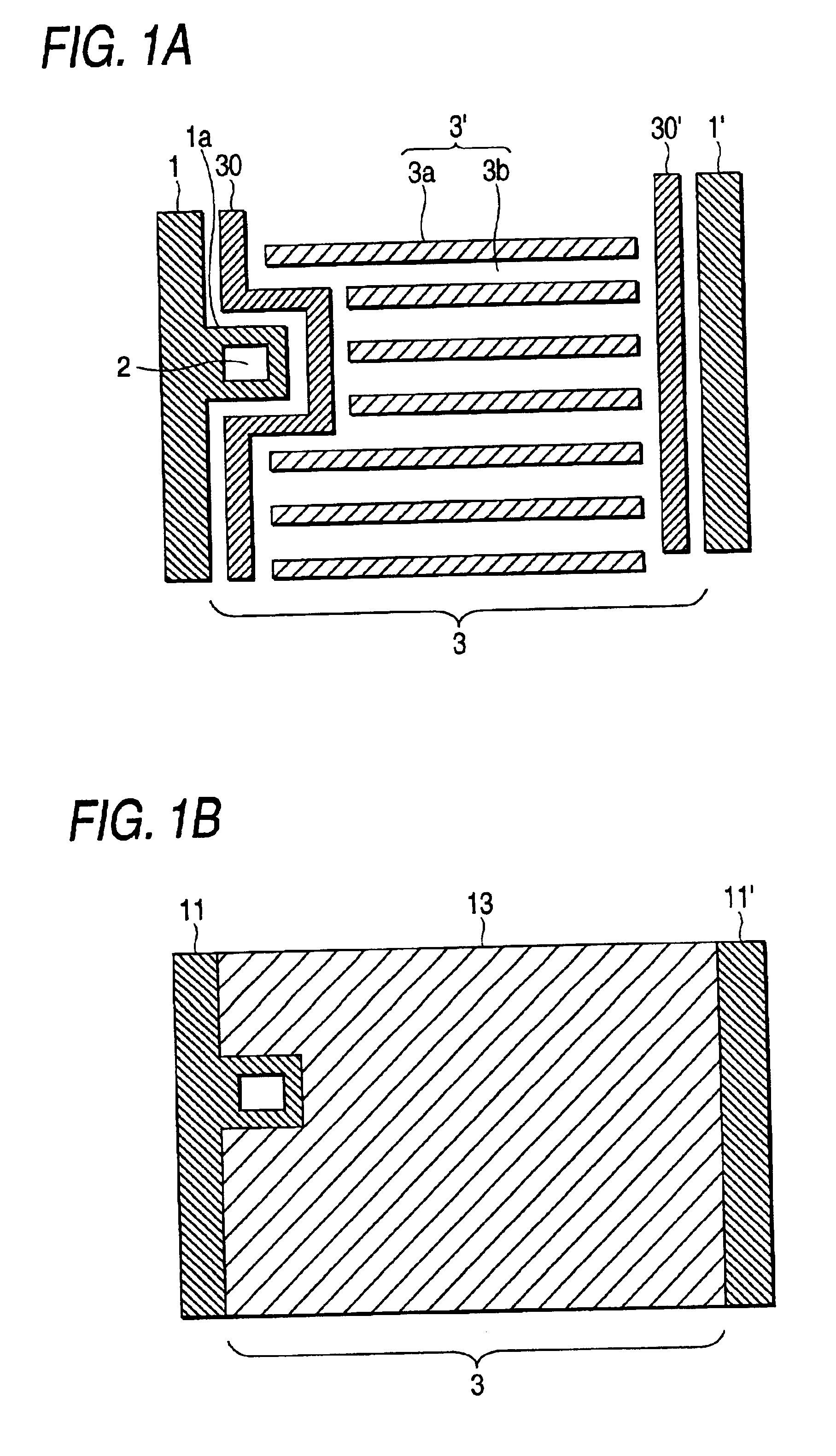
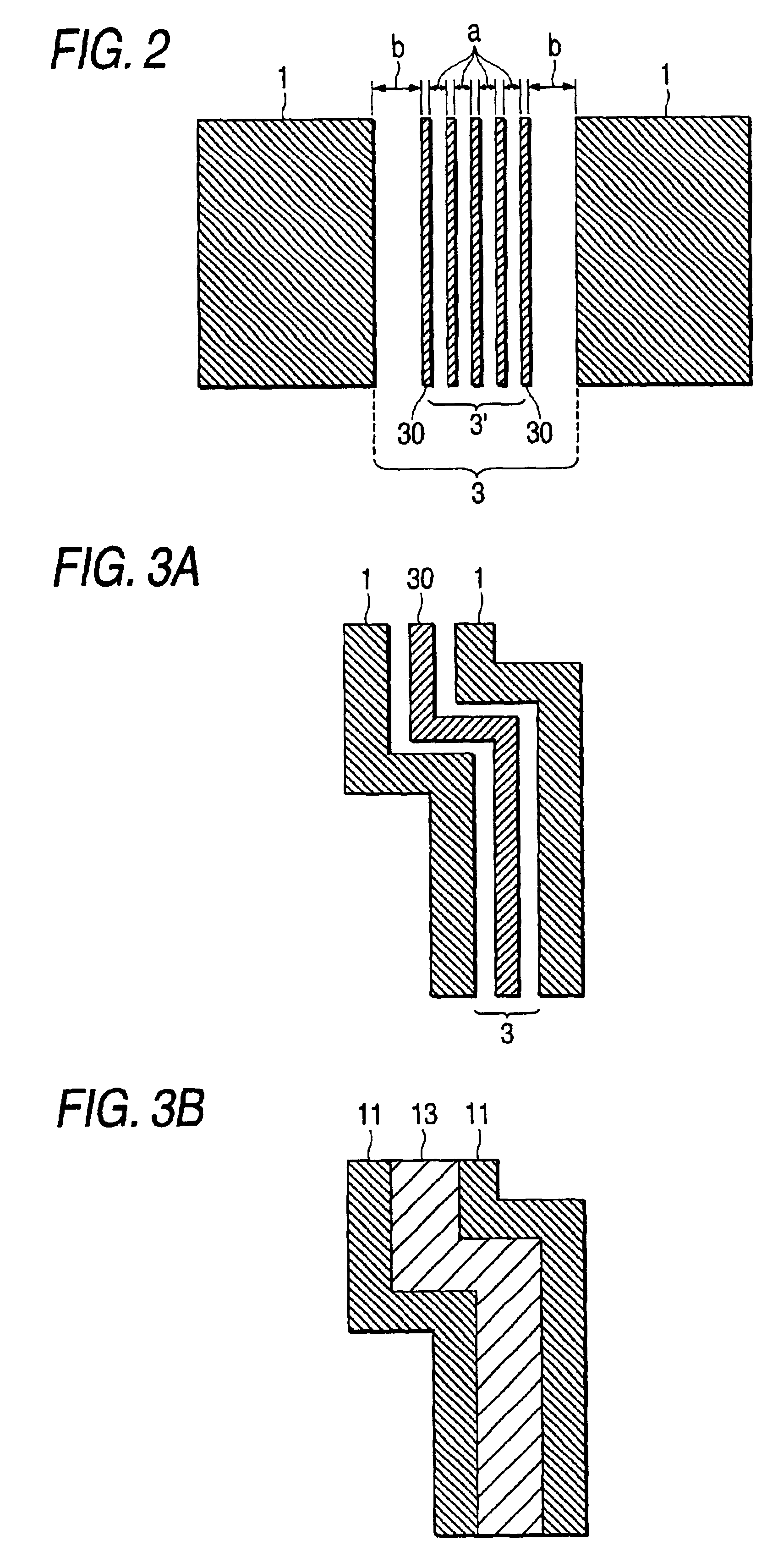
[0067]As shown in FIG. 2, the embodiment (third embodiment) is characterized in that, when the opaque pattern present in the graytone part 3 adjacent to the opaque part 1 is formed from the line-and-space pattern 3′ substantially parallel to the contour geometry of the opaque part 1, an interval “b” between the opaque part 1 and a opaque pattern 3c, the pattern being located in the position most close to the opaque part 1 within the gray tone part 3 adjacent to the opaque part 1, is larger than the space interval “a” of the line-and-space pattern 3′ (b>a).

[0068]According to the third embodiment, in contrast with the case of b=a, a resist pattern corresponding to the opaque part 1 can be formed with superior geometrical and dimensional accuracy. In short, in contrast with the case of b=a, in the case of b>a there can be achieved a greater function of forming a resist pattern corresponding to the main pattern with superior dimensional and geometrical accuracy, by means of the opaque p...

fourth embodiment

[0072]As shown in FIG. 3B, the resist patterns 11, 11 corresponding to the opaque parts 1, 1 can be formed with superior geometrical and dimensional accuracy. Further, the thin resist region 13 can be formed by means of interaction between the opaque parts 1, 1 and the contour pattern 30.

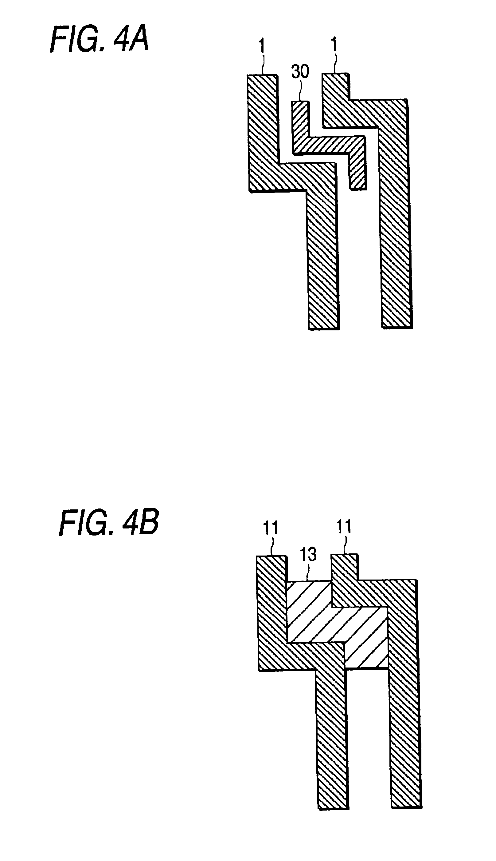
[0073]As shown in FIG. 4B, in the embodiment, the contour pattern 30 can be formed locally in only an area which requires formation of a graytone part. As shown in FIG. 4B, in the present case, bends of the resist patterns 11, 11 corresponding to the opaque parts 1, 1 can be formed with superior geometrical and dimensional accuracy. The thin resist region 13 can be formed in only the bends by means of interaction between the opaque parts 1, 1 and the contour pattern 30.

[0074]Still another embodiment will now be described.

[0075]As shown in FIG. 5A, this embodiment (Embodiment 1′) is for forming the contour pattern 30 in the area including the boundary part between the transmission part 2 and the gra...


PUM

PropertyMeasurementUnit
space widthaaaaaaaaaa
widthaaaaaaaaaa
sizeaaaaaaaaaa

Abstract

The invention is intended for commercializing a pattern transfer process using a graytone mask, wherein the mask has a graytone part constituted of a minute opaque pattern of a size smaller than a resolution limit of an aligner using a graytone mask. For example, a contour pattern 30 is formed in an area close to a graytone part 3 along a contour pattern of an opaque pattern 1 adjacent to the graytone part 3.

Description

BACKGROUND OF THE INVENTION[0002]1. Field of the Invention[0003]The invention relates to a graytone mask having a graytone part for obtaining an intermediate amount of transmission of light between that achieved in an opaque part and that achieved in a transmission part.[0004]2. Description of the Related Art[0005]In recent years, attempts have been made to reduce the number of mask sheets by using graytone masks in the field of large-sized LCD masks (as set forth in the monthly FPD Intelligence, May, 1999).[0006]As shown in FIG. 8A, such a graytone mask has an opaque part 1, a transmission part 2 and graytone part 3. The graytone part 3 corresponds to an area in which there is formed an opaque pattern 3a of below or equal to the resolution limit of an exposure apparatus for a large-sized LCD using the graytone mask and is designed to selectively change the thickness of a photoresist film by decreasing the light transmitted through this area so as to decrease the amount of irradiati...

Claims


Application Information

Patent Timeline
Patent Type & Authority Patents(United States)
IPC IPC(8): G03F1/14G03F1/54G03F7/20H01L21/027
CPCG03F1/144G03F1/50
Inventor IMURA, KAZUHISA
Owner HOYA CORP
Why Eureka
Try Eureka