Switching device

a switching device and drive body technology, applied in the direction of switches with two operating positions, electrical equipment, tumbler/rocker switch details, etc., can solve the problems of complicated structure, difficult assembly of the switching device, and large size of the overall switching device, so as to achieve convenient assembly, simple structure, and easy assembly.

Inactive Publication Date: 2005-01-11
ALPS ALPINE CO LTD
View PDF9 Cites 13 Cited by
  • Summary
  • Abstract
  • Description
  • Claims
  • Application Information

AI Technical Summary

Benefits of technology

In view of the problems of the conventional art, the present invention has been made. Accordingly, it is an object of the present invention to provide a switching device which has a compact, thin, and simple structure and is easy to assemble.
In the switching device having the above-mentioned structure, since the spring elastically urges the shaft of the drive body towards the bottom wall of the casing, when a pressing operation force is exerted, via an operating knob, on the pressing actuator of the drive body protruding sidewards from the casing, the sliding actuator of the drive body slides on the sloped surface of the conductive plate in conjunction with the turning of the drive body so as to turn the conductive plate. That is, the pressing actuator of the drive body can be directly pressed by the operating knob. Accordingly, since no other drive member for causing the conductive plate to come into contact with or to be detached from one of the stationery contacts is required to be interposed between the drive body and the operating knob, and also the spring can be disposed in a narrow space above the drive body, the overall structure of the switching device can be easily made thin. Also, since the push-switch disposed in the vicinity of the casing is actuated by the pressing actuator which is pressed down by the operating knob, no additional drive member for the push-switch is required to be disposed, thereby leading to a compact, thin, and simple structure. In addition, since the conductive plate, the drive body, and the spring are built on the bottom wall of the casing in that order, the switching device is easy to assemble.
Also, in any one of the above-mentioned structures, the casing may have two sets of switching elements disposed therein side by side, each including the group of stationery contacts, the conductive plate, the drive body, and the spring. This structure provides a double-pole double-throw switching device in which one of the switching elements outputs a first drive signal when the operating knob is pressed into one direction and the other switching element outputs a second drive signal when the operating knob is pressed into the other direction. In this case, preferably, the two groups of stationery contacts, the two conductive plates, and the two drive bodies of the two sets of switching elements are respectively disposed so as to be symmetric with respect to a point in plan view. Also, in the switching device having the foregoing structure, preferably, the casing has an opening opposing the bottom wall; each of a plurality of the corresponding sidewalls, which are disposed in the casing in a standing manner so as to be parallel to each other, has a depression formed so as to be open towards the opening and having the shaft of the corresponding drive body inserted therein so as to be movable upwards and downwards; and each of another plurality of the corresponding sidewalls, which are disposed in the casing so as to be at a right angle with the former sidewalls, has a slit formed so as to be open towards the opening and having a portion of the corresponding drive body for supporting the pressing actuator inserted therein so as to be movable upwards and downwards. With this structure, the overall structure of the switching device is easily made thin.

Problems solved by technology

Accordingly, as described above, when a pressing drive rod or a pressing drive body for actuating a push-switch is additionally disposed in such a switching device, the overall switching device including the pressing drive rod protruding downward or the pressing drive body protruding sidewards becomes considerably large and also its structure becomes complicated.
When the known switching device shown in FIG. 12 is assembled, the drive body 4 incorporated into the recess 6a of the turning lever 6 together with the coil spring 5 must be disposed on the conductive plate 3 in the casing 1; however, since this assembling step must be carefully performed such that the drive body 4 and the coil spring 5 do not drop off from the turning lever 6, the switching device is difficult to assemble.
As a result, when a pressing drive rod or a pressing drive body for actuating a push-switch is additionally disposed in such a switching device, the switching device becomes more difficult to assemble, thereby leading to a reduced productivity.

Method used


Image

  • Switching device
  • Switching device
  • Switching device

Examples


Embodiment Construction

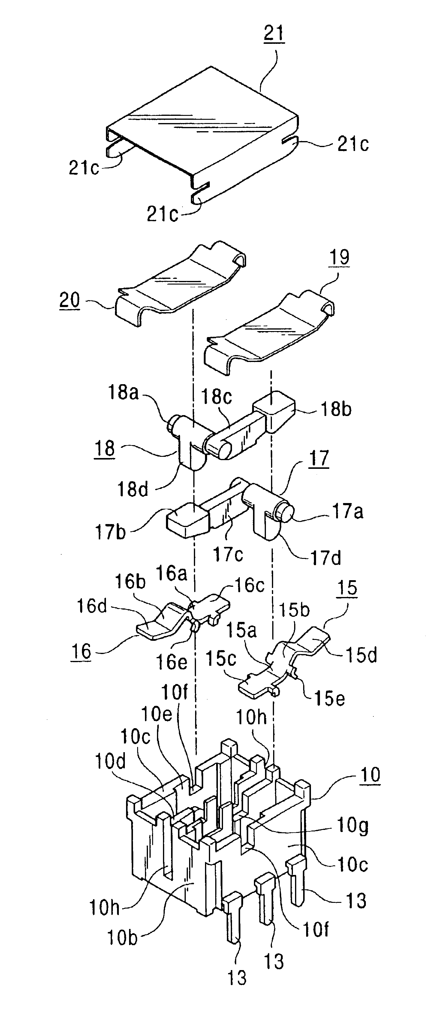
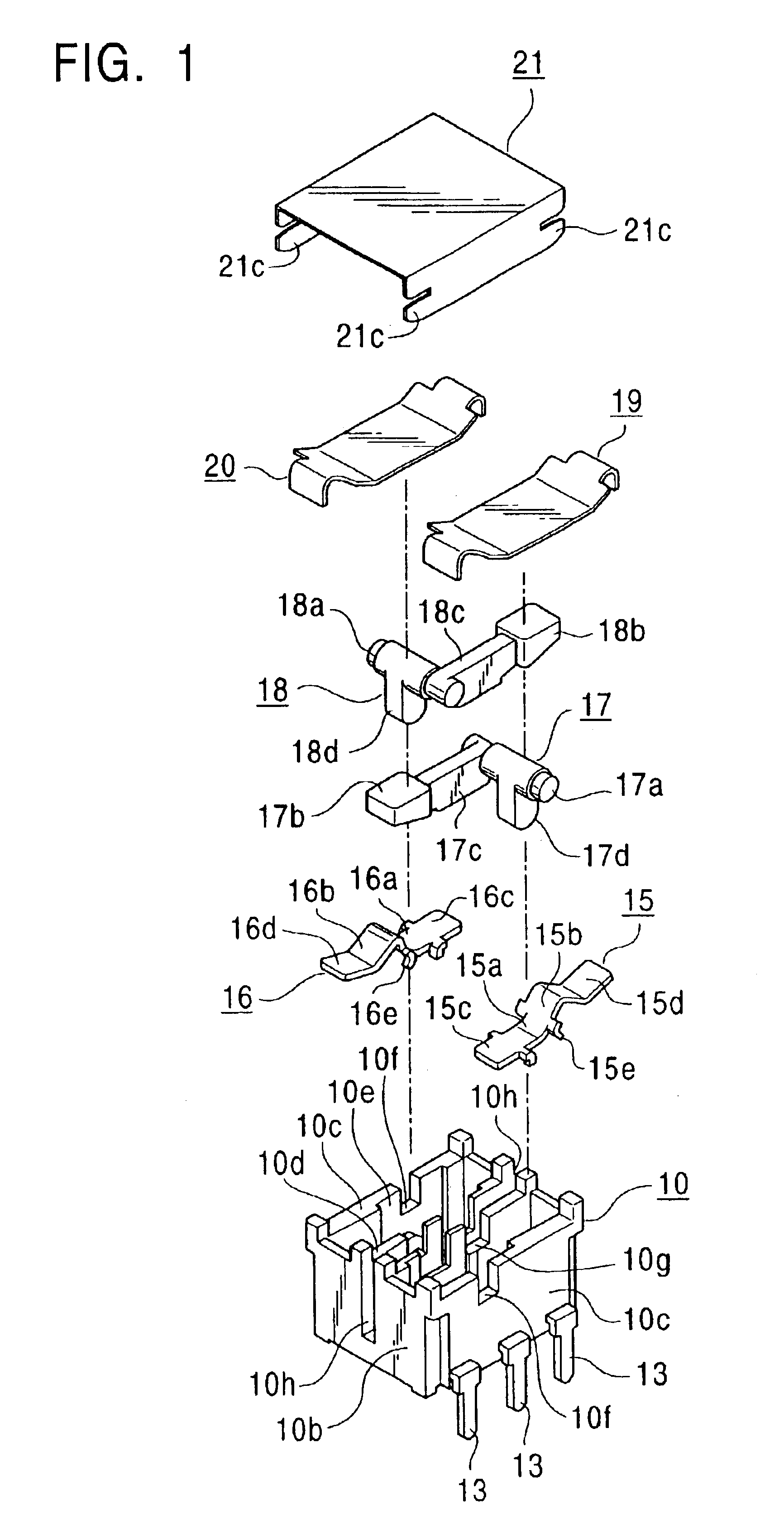
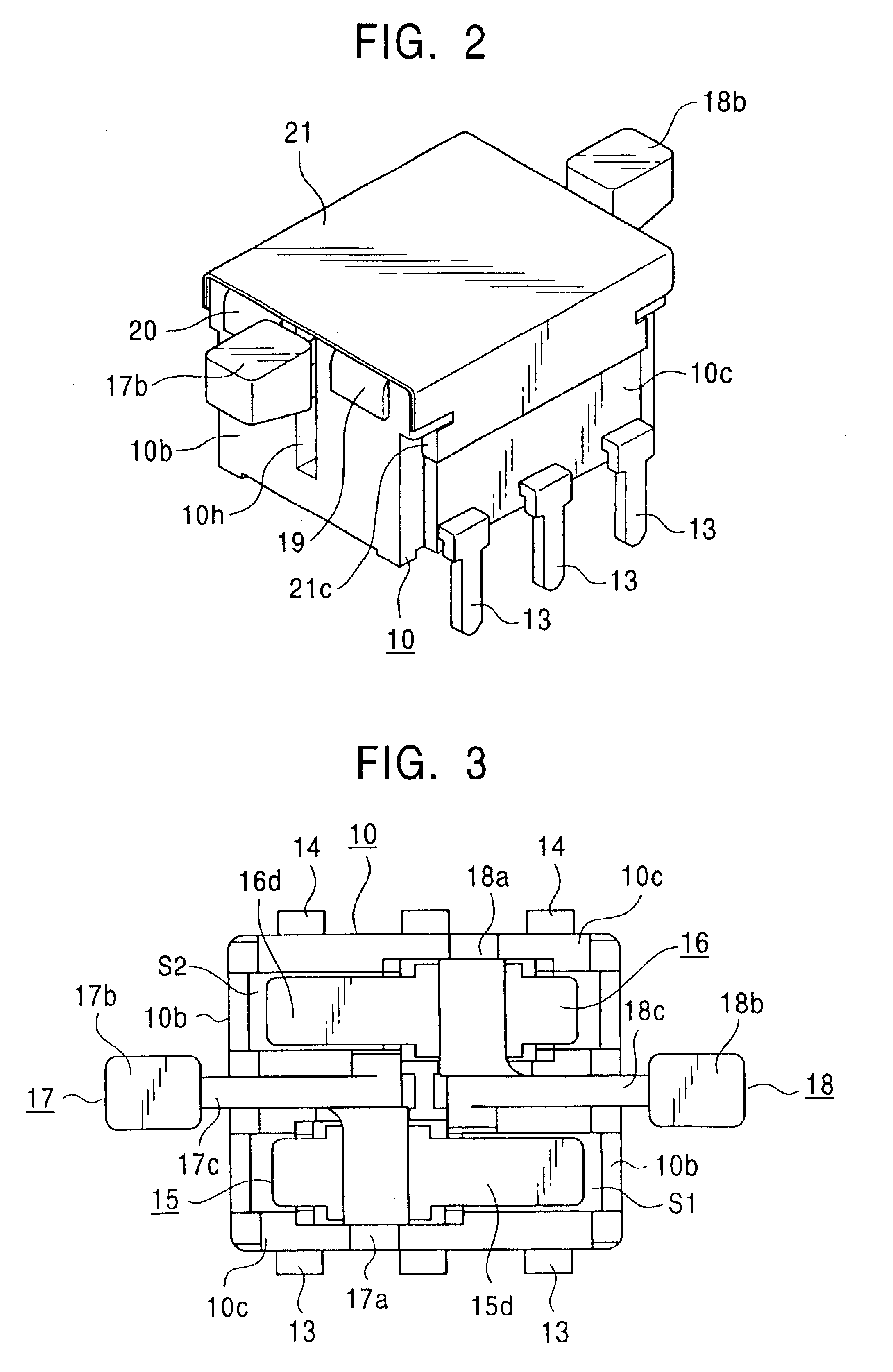
A preferred embodiment of the present invention will be described with reference to the accompanying drawings. FIG. 1 is an exploded perspective view of a switching device according to the embodiment of the present invention. FIG. 2 is a perspective view of the switching device. FIG. 3 is a plan view of the switching device in which a cover and a leaf spring are omitted. FIG. 4 is a plan view of a casing used for the switching device. FIG. 5 illustrates a non-operational state of the switching device. FIGS. 6 and 7 illustrate the states in which a conductive plate is turned and a push switch is actuated, respectively, by operating the switching device. FIG. 8 is a plan view of the switching device. FIGS. 9 and 10 are side views of the switching device viewed from its long side and short side, respectively. FIG. 11 is a bottom view of the switching device.

The switching device illustrated in these figures is used as a drive switch of a car-mounted automatic window apparatus and is a d...


PUM


Abstract

A switching device includes three stationery contacts fixed to a casing and exposed on a bottom wall of casing, a conductive plate swingable about the central contact as a fulcrum and coming into contact with or detached from one of the other contacts, a drive body disposed on the conductive plate so as to be movable upwards and downwards and turnable about a shaft thereof, and a leaf spring elastically urging the shaft towards the bottom wall. The drive body has a pressing actuator protruding sidewards from the casing. When the pressing actuator is pressed by an operating knob so as to turn the drive body by a predetermined amount, a sliding actuator of the drive body slides on the conductive plate so as to turn the conductive plate. When the drive body is turned by another predetermined amount, the pressing actuator actuates a push-switch disposed near the casing.

Description

BACKGROUND OF THE INVENTION1. Field of the InventionThe present invention relates to switching devices which are operated in a swinging manner and more particularly it relates to a switching device which outputs two-position change-over signals with a consecutive pressing operation and which is suitable for use in a drive switch of a car-mounted automatic widow apparatus and the like.2. Description of the Related ArtFIG. 12 is a sectional view of a known switching device of the above-mentioned type. As shown in the figure, a casing 1 having a bottom wall 1a has first, second, and third stationery contacts 2a, 2b, and 2c fixed therein by insert-molding and has three terminals 8 extending from the corresponding stationery contacts 2a to 2c and protruding downwards from the casing 1. Each of the stationery contacts 2a to 2c is exposed on the bottom wall 1a of the casing 1 and the central stationery contact 2a has a conductive plate 3 swingably disposed thereon, serving as a fulcrum the...

Claims


Application Information

Patent Timeline
Patent Type & Authority Patents(United States)
IPC IPC(8): H01H23/00H01H23/16H01H23/02
CPCH01H23/168H01H23/006H01H2300/01H01H23/24
Inventor SASAKI, MAKOTOSAWADA, KENJI
Owner ALPS ALPINE CO LTD
Why Eureka
Try Eureka