Circuit breaker magnetic trip assembly

a circuit breaker and magnetic trip technology, applied in the field of circuit breakers, can solve the problems of not generating enough force to trip the circuit breaker at lower amperage, and the cost of multi-turn coils is more expensive than the core/armature design,

Inactive Publication Date: 2005-01-11
ABB SPA
View PDF5 Cites 12 Cited by
  • Summary
  • Abstract
  • Description
  • Claims
  • Application Information

AI Technical Summary

Benefits of technology

The above discussed and other drawbacks and deficiencies are overcome or alleviated by a magnet assembly for actuating a trip latch in a circuit breaker. The magnet assembly includes a core and an armature. The core is disposed around a conductor forming a primary current path in the circuit breaker, and includes an end forming a pole face. The armature is biased by a force acting in a direction away from the pole face. The armature includes a generally planar surface and a projection extending from the generally planar surface toward the pole face. The generally planar surface is separated from the pole face by a first air gap, and the projection is separated from the pole face by a second air gap. The first air gap is larger than the second air gap. A magnetic field induced in the first and second air gaps by the passage of electrical current through the conductor moves the armature against the force to actuate the trip latch. The armature may be generally L-shaped, with one end of the armature being pivotally secured proximate an opposite end of the core and the other end forming the projection. The core may be generally U-shaped, with a portion of a leg of the core including the pole face being bent to offset the portion by a distance greater than about the thickness of the projection. The projection is received in a space formed by the offset.
In one embodiment, the force is applied by a spring coupled between the armature and the opposite end of the core. The spring may be secured to the armature by a bracket. One end of the bracket and one end of the armature may extend through an aperture in the opposite end of the core with the bracket including a tab extending therefrom for retaining the armature and the bracket within the aperture.

Problems solved by technology

While such magnetic trip assemblies work well for high ampere ratings, they may not generate enough force to trip the breaker at lower amperages (e.g., 12.5 times the circuit breaker ampere rating for current ratings 30 amps and above) because of the large air gap inherent in these designs.
Such multi-turn coils are, however, more expensive than the core / armature design.

Method used


Image

  • Circuit breaker magnetic trip assembly
  • Circuit breaker magnetic trip assembly
  • Circuit breaker magnetic trip assembly

Examples


Embodiment Construction

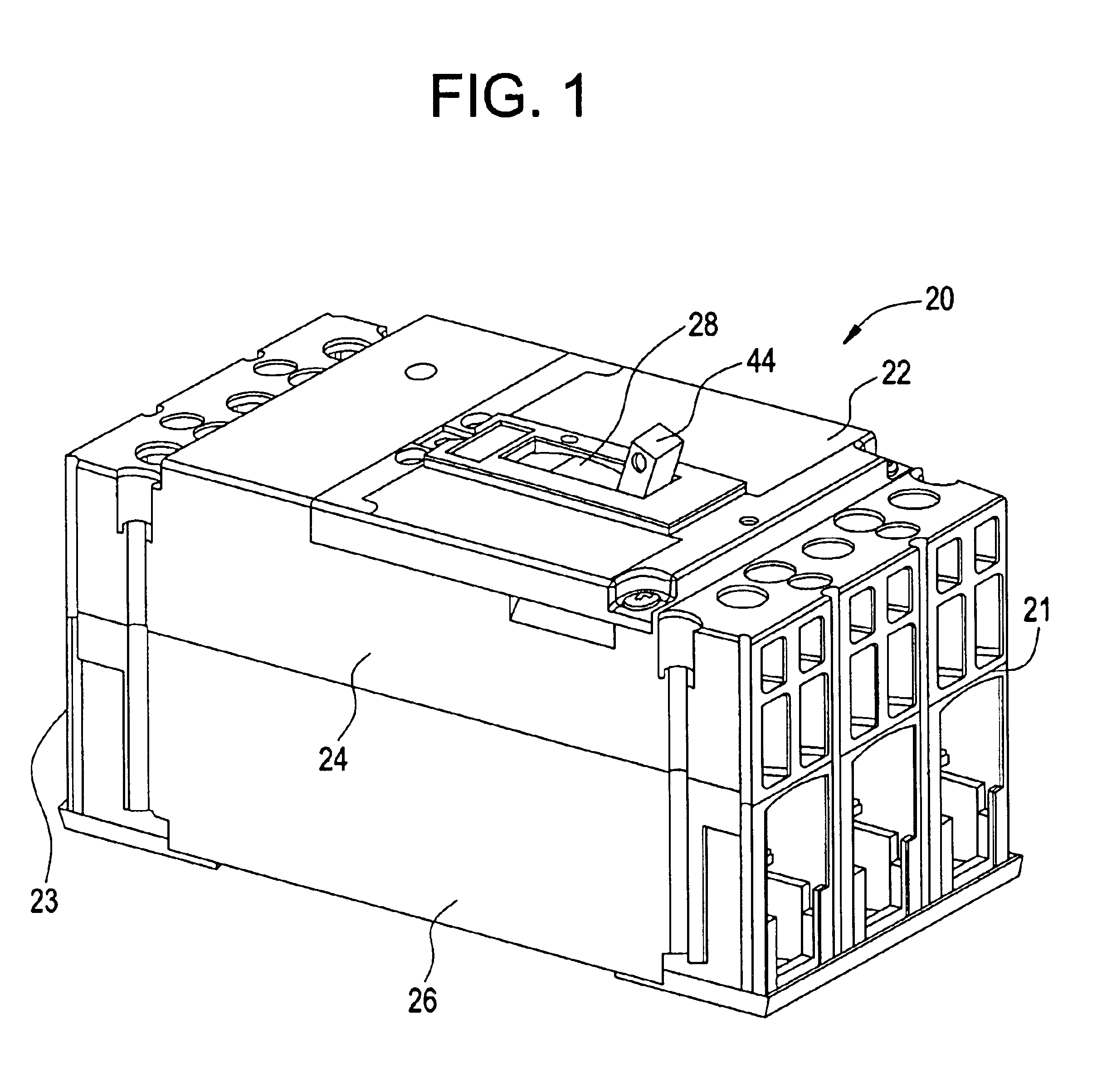
Referring to FIG. 1, a top perspective view of a molded case circuit breaker 20 is generally shown. Molded case circuit breaker 20 is generally interconnected within a protected circuit between multiple phases of a power source (not shown) at line end 21 and a load to be protected (not shown) at load end 23. Molded case circuit breaker 20 includes a base 26, a mid cover 24 and a top cover 22 having a toggle handle (operating handle) 44 extending through an opening 28.

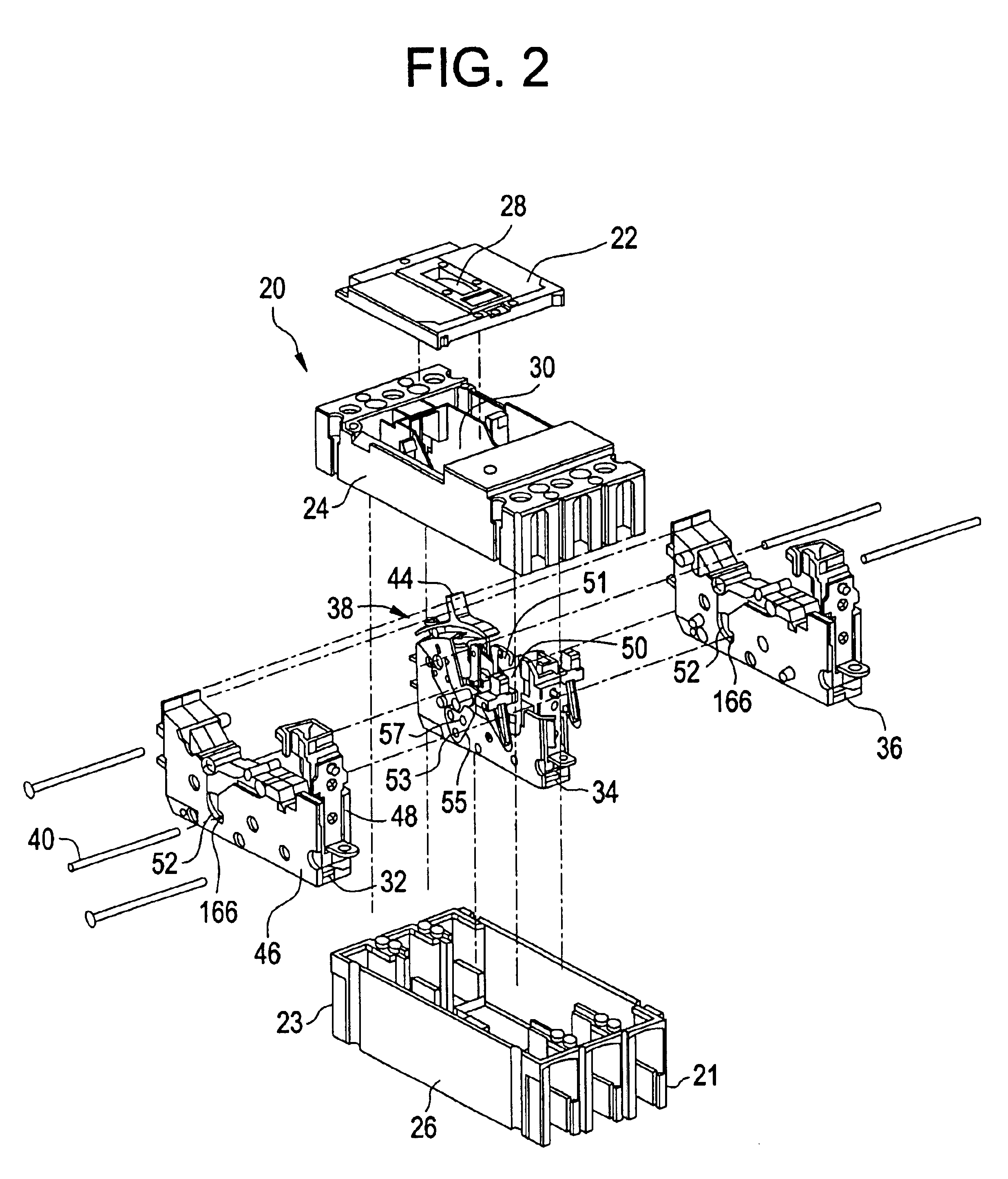
FIG. 2 shows an exploded view of the circuit breaker 20. Disposed within base 26 are a number of cassettes 32, 34, and 36, corresponding to the number of poles (phases of current) in the electrical distribution circuit into which circuit breaker 20 is to be installed. The example shown corresponds to a 3-pole system (i.e., three phases of current), and has three cassettes 32, 34 and 36 disposed within base 26. It is contemplated that the number of cassettes can vary corresponding to the number of phases. Cassettes 32, 3...


PUM


Abstract

A magnet assembly for actuating a trip latch in a circuit breaker. The magnet assembly includes a core and an armature. The core is disposed around a conductor forming a primary current path in the circuit breaker, and includes an end forming a pole face. The armature is biased by a force acting in a direction away from the pole face. The armature includes a generally planar surface and a projection extending from the generally planar surface toward the pole face. The generally planar surface is separated from the pole face by a first air gap, and the projection is separated from the pole face by a second air gap. The first air gap is larger than the second air gap.

Description

BACKGROUND OF THE INVENTIONThe present invention relates to circuit breakers and, more particularly, to magnetic trip assemblies for circuit breakers.Circuit breakers typically provide instantaneous, short time, and long-time protection against high currents produced by various conditions such as short-circuits, ground faults, overloads, etc. In a circuit breaker, a trip unit is the device that senses current (or other electrical condition) in the protected circuit and responds to high current conditions by tripping (unlatching) the circuit breaker's operating mechanism, which in turn separates the circuit breaker's main current-carrying contacts to stop the flow of electrical current to the protected circuit. Such trip units are required to meet certain standards, e.g., UL / ANSI / IEC, which define trip time curves specifying under what conditions a trip must occur, i.e., short time, long time, instantaneous, or ground fault, all of which are well known.One type of trip unit used for ...

Claims


Application Information

Patent Timeline
Patent Type & Authority Patents(United States)
IPC IPC(8): H01H71/24H01H71/12
CPCH01H71/2472
Inventor CIARCIA, RONALDBRIGNONI, LUISMACHA, NARENDERSUBRAMANIAN, ANANTHARAMKIM, SAMUEL STEPHEN
Owner ABB SPA
Why Eureka
Try Eureka