
Data striping based switching system

Inactive Publication Date: 2005-01-11
TELEFON AB LM ERICSSON (PUBL)
View PDF27 Cites 131 Cited by
  • Summary
  • Abstract
  • Description
  • Claims
  • Application Information

AI Technical Summary

Problems solved by technology

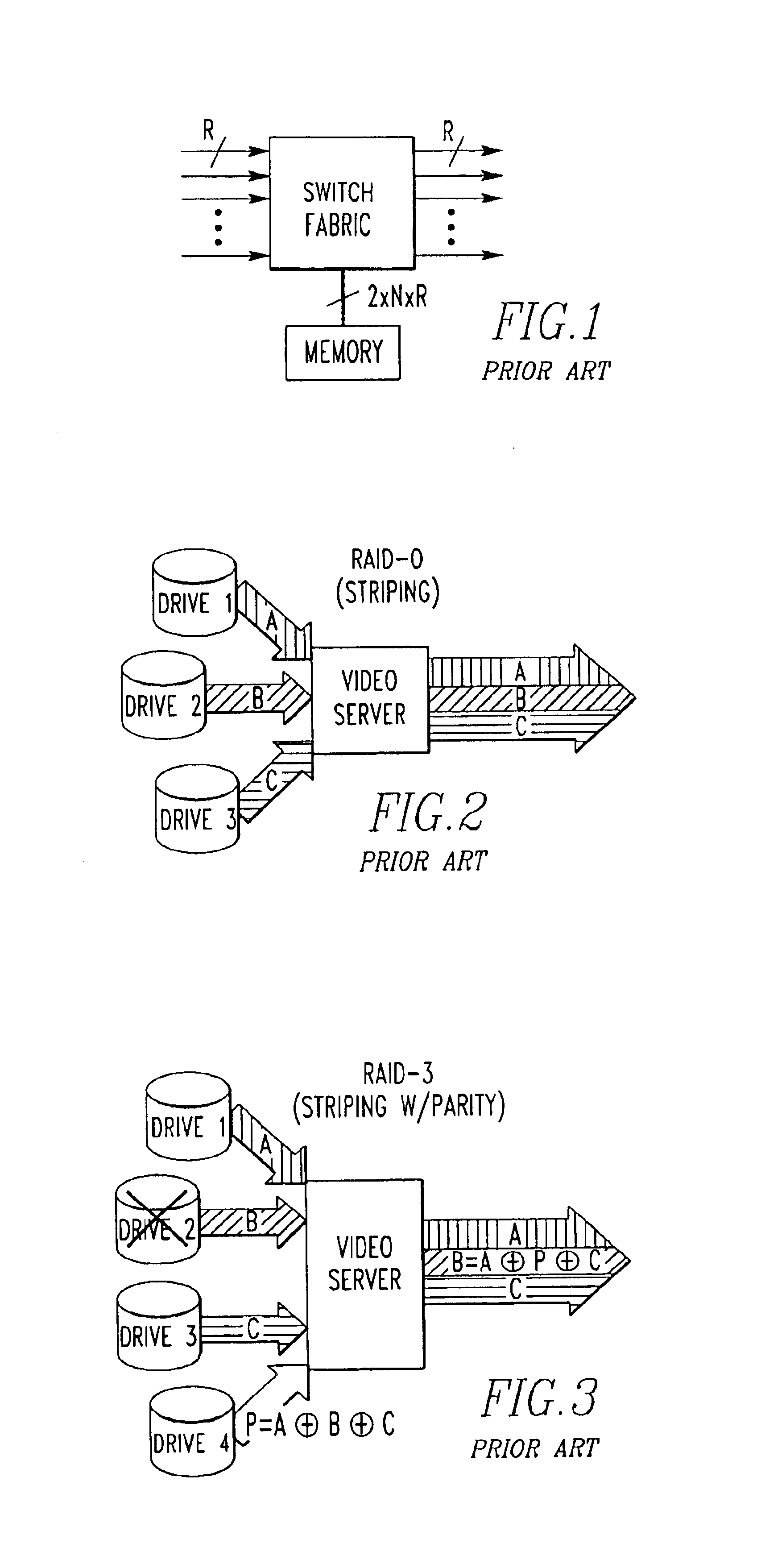
Although practical for small to medium sized switching systems, a TDM switch is limited in throughput by the bandwidth of the centralized memory bus.
Although greater scaling is permitted with separate queues, performance usually suffers.

Method used


Image

  • Data striping based switching system
  • Data striping based switching system
  • Data striping based switching system

Examples


Embodiment Construction

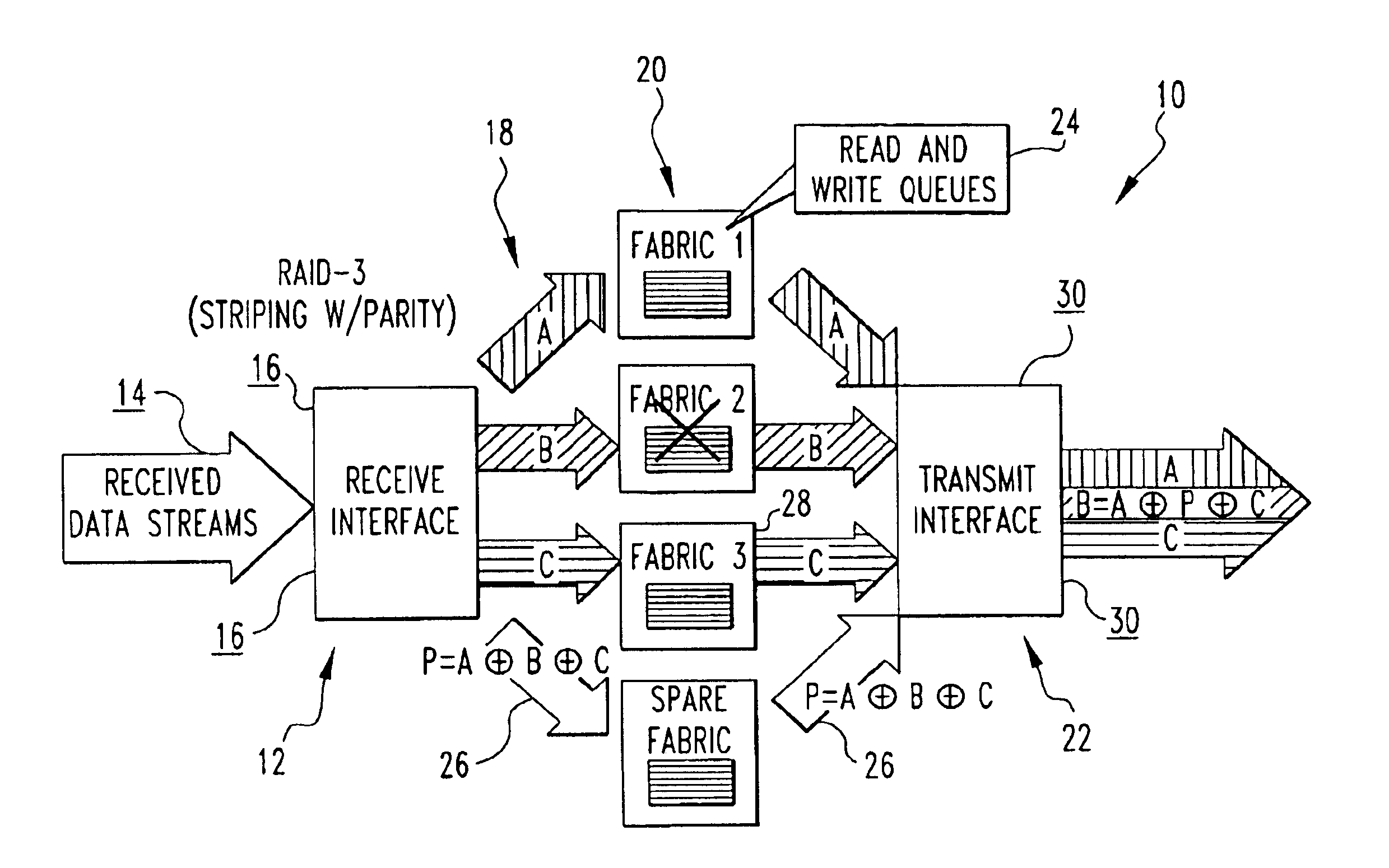
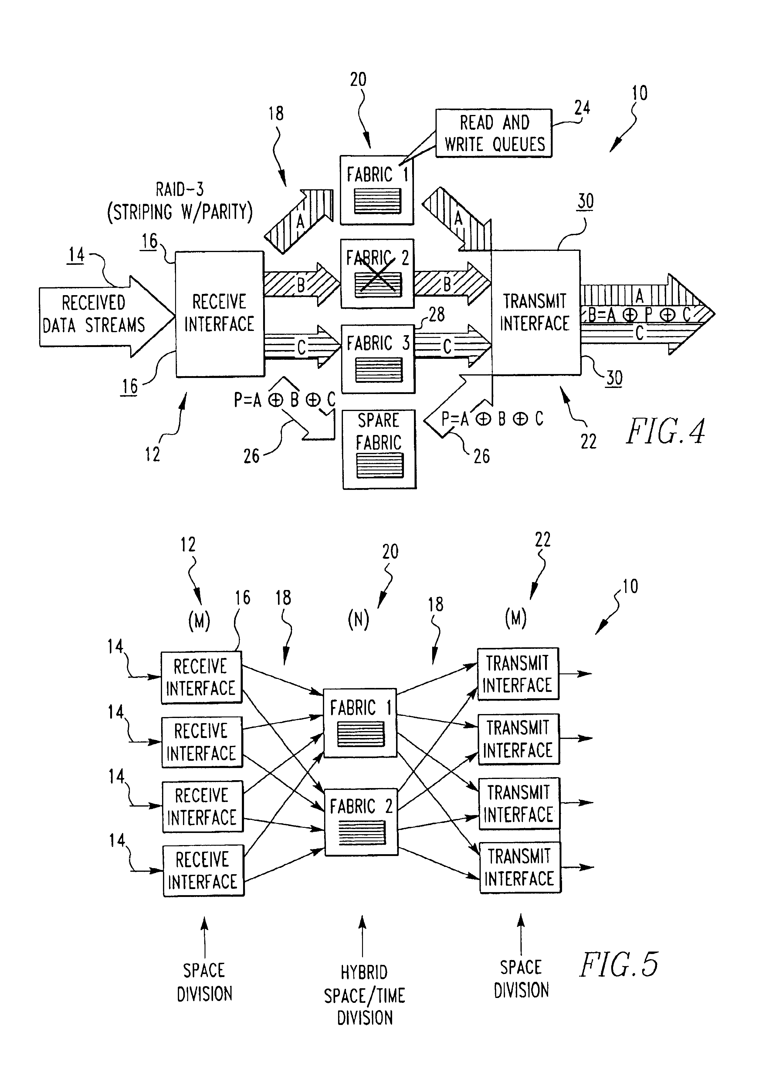
Referring now to the drawings wherein like reference numerals refer to similar or identical parts throughout the several views, and more specifically to FIGS. 4 and 5 thereof, there is shown a switching system 10. The system 10 comprises M receive interfaces 12 each of which receive a data stream 14, where M is greater than or equal to 1 and is an integer. At least a first receive interface 16 of the M receive interfaces 12 produces S stripes 18 of the data stream 14, where S is greater than or equal to 2 and is an integer. The system 10 comprises N switch fabrics 20, where N is greater than or equal to 2 and is an integer. At least a first and second of the N switch fabrics 20 each receive 1 of the N stripes 18 of the data stream 14 from the first of the M receive interfaces 12. Each switch fabric is connected to at least one of the M receive interfaces 12. The system 10 comprises O transmit interfaces 22, where O is greater than or equal to 1 and is an integer. At least a first of...


PUM


Abstract

A switching system for a data stream utilizing striping with a parity stripe, so if a fabric of the system fails, the data stream can still be reconstructed with the parity stripe. The system uses receive and transmit interfaces which implement space division, and fabrics which implement hybrid space / time division.

Description

FIELD OF THE INVENTIONThe present invention is related to a switching system which uses stripes of data from a data stream to implement a switching system receives to switch the data stream. More specifically, the present invention is related to a switching system which uses stripes of data from a data stream that the switching system receives to switch the data stream. A parity stripe can be used such that less than all of the stripes are required to reconstruct the data stream if one of the stripes is lost.BACKGROUND OF THE INVENTIONTime division multiplexing (TDM) is one technique used to implement a switching system. A TDM switch consists of a central resource that operates at a bandwidth equal to the sum of the input and output port bandwidths. The central resource is partitioned via time slots that are allocated to the input and output ports. Typically, the central resource is a memory bus that writes packets that are received on the input ports and reads packets to be transmi...

Claims


Application Information

Patent Timeline
IPC IPC(8): H04Q11/06H04N7/08H04J3/00H04N7/081H04Q3/52H04Q3/68
CPCH04Q3/68H04Q11/06H04Q2213/1302H04Q2213/1304H04Q2213/13103H04Q2213/13166H04Q2213/13393H04Q2213/13174H04Q2213/13215H04Q2213/13292H04Q2213/13337H04Q2213/1334H04Q2213/13167
Inventor BIANCHINI, JR., RONALD P.
Owner TELEFON AB LM ERICSSON (PUBL)
Learn More