Blade attachment for an all-terrain vehicle

a technology for all-terrain vehicles and blades, which is applied in the field of blade attachments for off-road vehicles, can solve the problems of inconvenient blade adjustment and the operator's dismounting from the atv

Inactive Publication Date: 2005-01-18
KOLPIN OUTDOORS
View PDF13 Cites 59 Cited by
  • Summary
  • Abstract
  • Description
  • Claims
  • Application Information

AI Technical Summary

Benefits of technology

A blade attachment for an off-road vehicle such as an all-terrain vehicle (ATV) is described with the ATV having a forward end, a rearward end, a right side, a left side, and an underside. A mounting frame or push tube assembly is positioned beneath the forward end of the ATV and has its rearward end pivotally connected, about a horizontal axis, to the ATV. The mounting frame extends forwardly from its rearward end so that its forward end is positioned forwardly of the forward end of the ATV. The forward end of the mounting frame is selectively movable between raised and lowered positions by any conventional means such as a lift handle, winch, linear actuator, etc. A first plate is secured to the forward end of the mounting frame and has a hinge plate selectively pivotally movably positioned thereon about a vertical axis with the hinge plate having a forward end and a rearward end. The hinge plate has a blade position lever opening formed therein. The hinge plate also has a plurality of spaced-apart notches formed in its rearward end. The blade is secured to the hinge plate in conventional fashion so as to be positioned forwardly thereof. A blade position lever i

Problems solved by technology

The requirement of the operator to dismount from the ATV and make the blade adjustment is inconvenient i

Method used


Image

  • Blade attachment for an all-terrain vehicle
  • Blade attachment for an all-terrain vehicle
  • Blade attachment for an all-terrain vehicle

Examples


Embodiment Construction

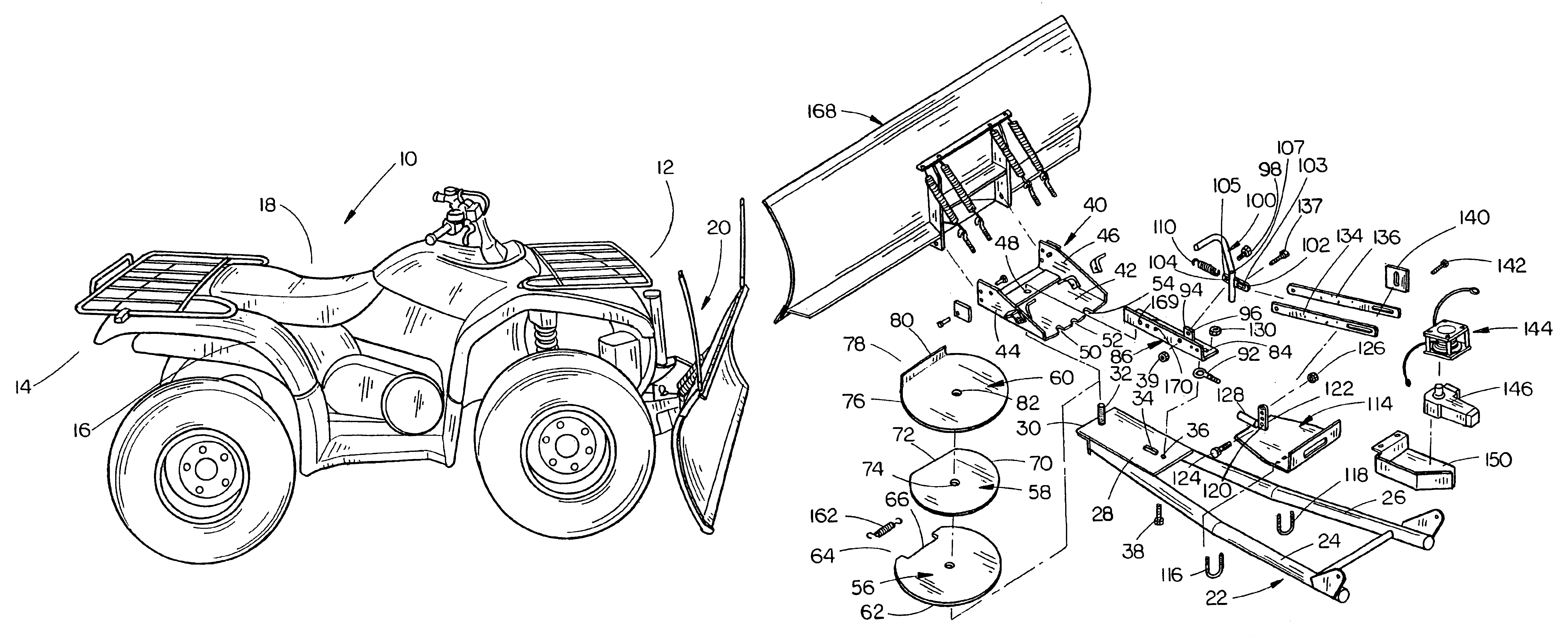
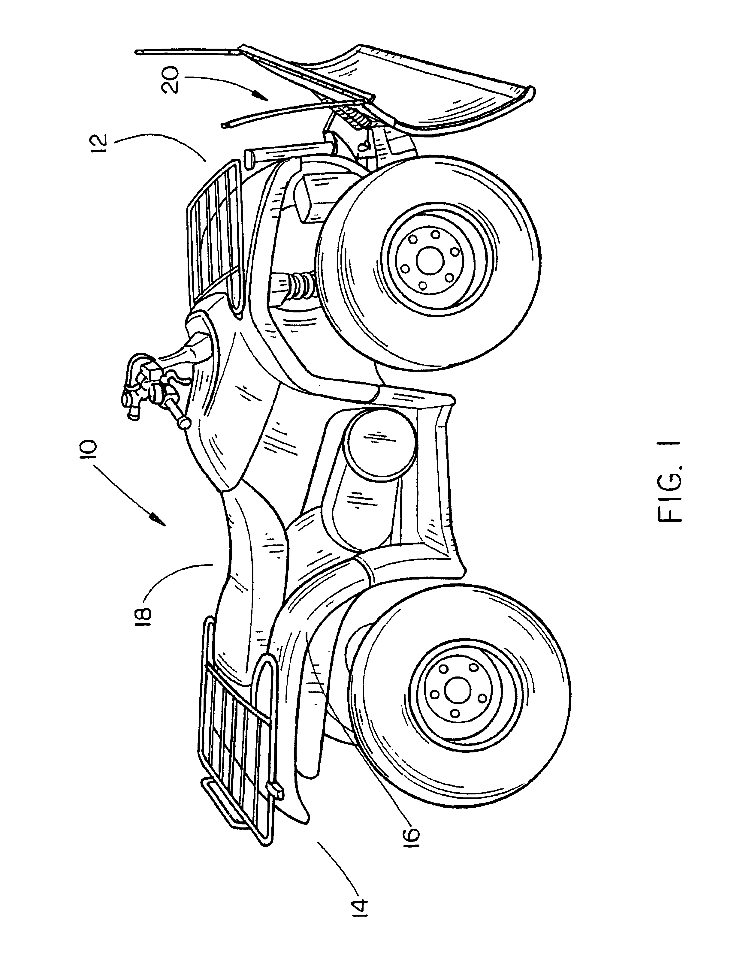
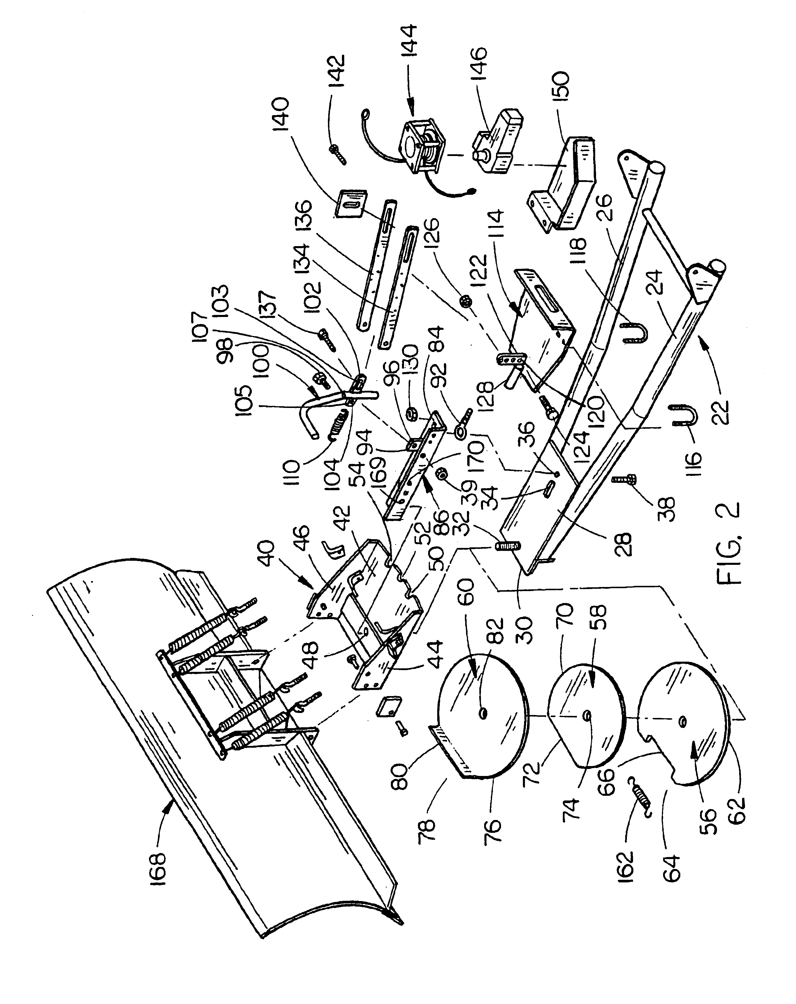
The numeral 10 refers generally to an off-road vehicle such as an all-terrain vehicle (ATV), which may be 2-wheel drive or 4-wheel drive. ATV 10 includes a forward end 12, rearward end 14, a right side 16, and a left side 18. The blade attachment of this invention is referred to generally by the reference numeral 20. Attachment 20 includes a push tube assembly 22 comprising push tubes 24, 26 which have their rearward ends pivotally secured to the frame of the ATV by a pin or pins (not shown) in conventional fashion. Support plate 28 is welded or otherwise secured to the forward ends of push tubes 24, 26 and has its forward end 30 positioned forwardly of the forward ends of push tubes 24, 26. Threaded bolt or stud 32 extends upwardly from the forward end of plate 28, as seen in FIG. 2. Plate 28 has a longitudinally extending blade position lever slot or opening 34 formed therein forwardly of the rearward end thereof. Plate 28 also has an opening 36 formed therein rearwardly of slot 3...


PUM


Abstract

A blade attachment for an off-road vehicle such as an ATV is provided. A mounting frame is pivotally connected at its rearward end to the ATV rearwardly of the forward end thereof. A hinge plate is pivotally mounted, about a vertical axis, to the forward end of the mounting frame and has the blade of this invention mounted thereon to enable the blade to be pivoted left, right, or positioned in a straight position. The blade is locked in its various positions by a blade position lever. A linkage is mounted on the forward end of the push tube assembly which is operatively connected to the blade position lever for moving the blade position lever between its locked and unlocked positions. The blade position lever is automatically moved to its unlocked position upon the linkage engaging the underside of the ATV. A winch is operatively connected, in a slip clutch fashion, to the hinge plate to enable the blade to be pivotally moved, about a vertical axis, between its various angular positions, when the blade position lever is in its unlocked position through the linkages.

Description

BACKGROUND OF THE INVENTION1. Field of the InventionThis invention relates to a blade attachment for an off-road vehicle such as an all-terrain vehicle (ATV) and more particularly to a blade attachment for an ATV wherein the angle of the blade may be conveniently selectively changed by means of an electric motor driven winch which is powered by the ATV electrical system.2. Description of the Related ArtThe assignee of this invention has manufactured straight and V-blades for ATVs for many years. The blades may be used to plow snow, dirt, etc. The prior art blades have been raised and lowered with respect to the ATV by lift handles, electric actuators, electric winches, etc. In assignee's prior art straight blade, the blade is selectively pivotally attached, about a vertical axis, to the forward end of a push tube assembly which is pivotally connected at its rearward end, about a horizontal axis, to the ATV. The blade is pivotally connected to the push tube assembly so that the blade...

Claims


Application Information

Patent Timeline
IPC IPC(8): E01H5/06E01H5/04E02F3/76
CPCE02F3/7613E01H5/06
Inventor MOFFITT, CHADRON D.
Owner KOLPIN OUTDOORS
Why Eureka
Try Eureka