
Multifunctional winch drum drive system

Inactive Publication Date: 2007-09-18
GROWTH INNOVATION
View PDF15 Cites 63 Cited by
  • Summary
  • Abstract
  • Description
  • Claims
  • Application Information

AI Technical Summary

Benefits of technology

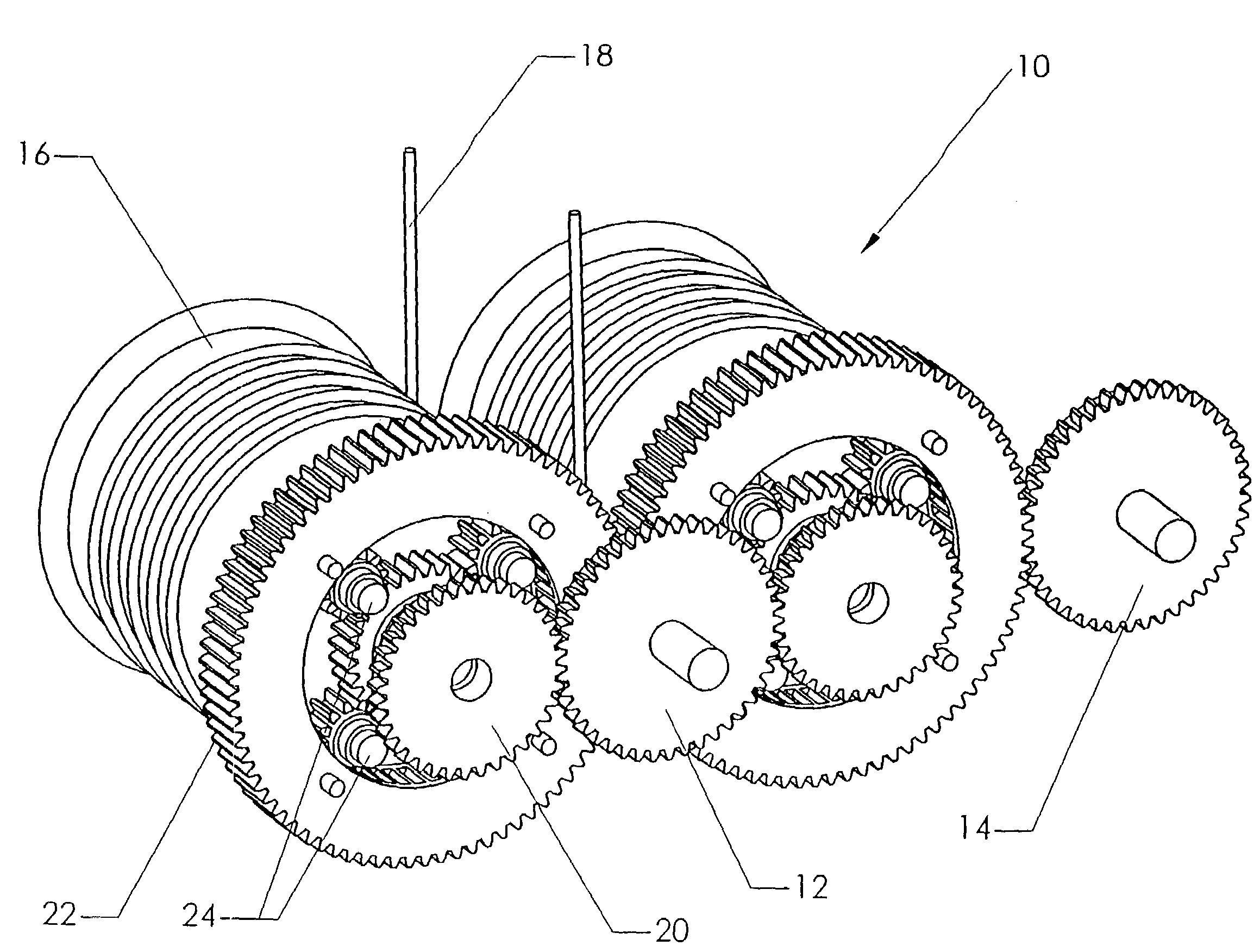
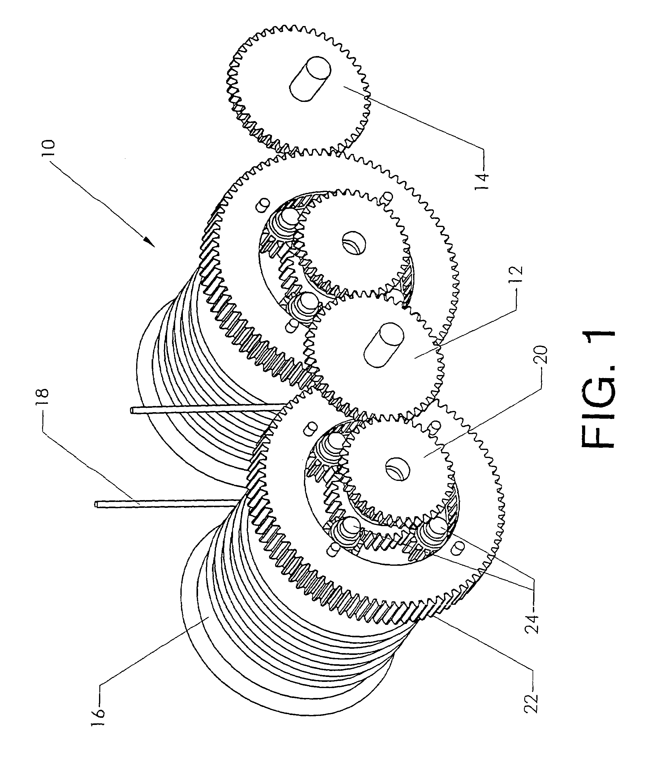
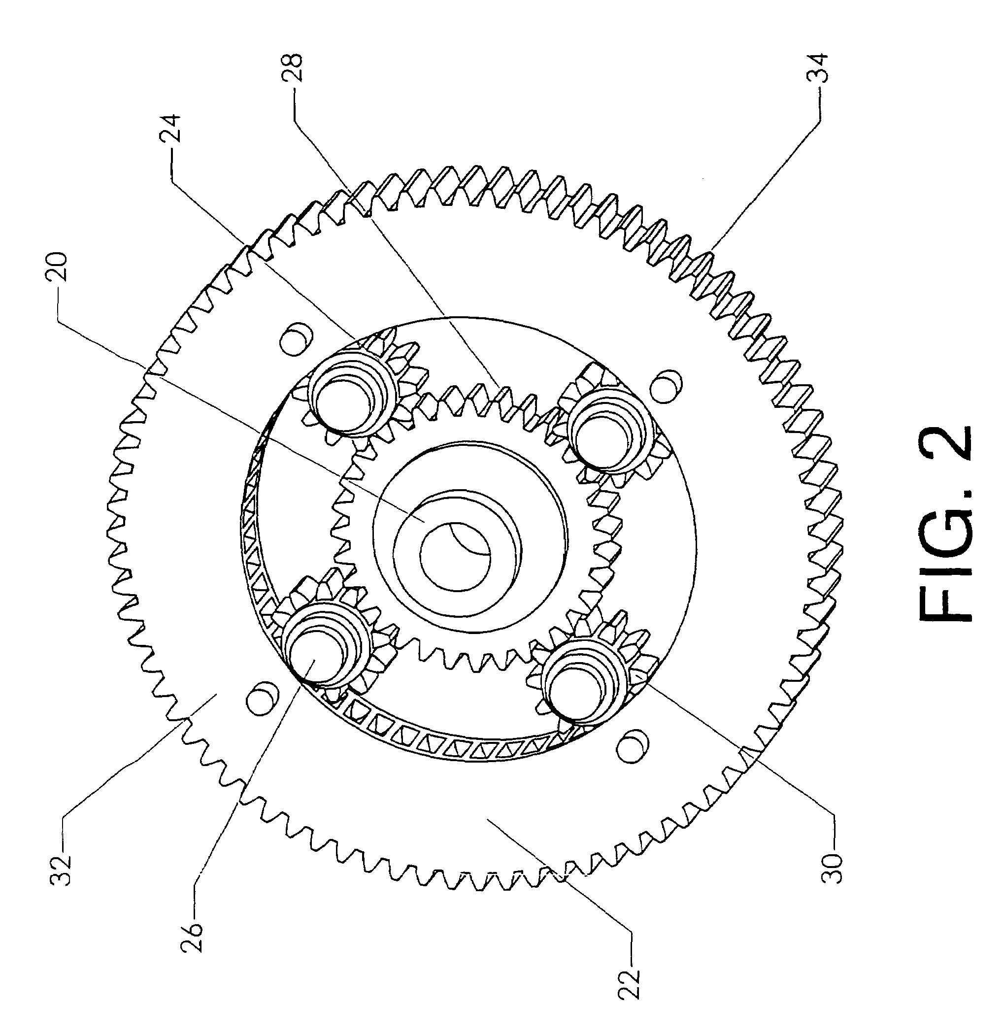
[0007]The present invention comprises a winch drum drive system. The winch drum drive system includes spools for winding and unwinding lines and a set of planetary gears rotatably attached to one end of each of the spools. The winch drum drive system is configured to be operable in two states. In the first state, the spools rotate in the same direction. In the second state, the spools rotate in opposite directions. Each state can further be operated in forward mode or reverse mode. Accordingly, in a two-spool system, the user can either rotate both spools clockwise, both spools counterclockwise, or rotate one spool clockwise while the other rotates counterclockwise. This feature provides a user with full control over the rotation of all spools, and the lines attached thereto, using a single gearbox.

Problems solved by technology

Traditional sail boats experience a heeling moment which causes the vessel to tilt.
Although the use of kites to power watercraft is a well-known idea, several limitations have prevented widespread acceptance.
Larger watercraft require larger kites, and larger kites can be complex to control.

Method used


Image

  • Multifunctional winch drum drive system
  • Multifunctional winch drum drive system
  • Multifunctional winch drum drive system

Examples


Embodiment Construction

[0016]The present invention, winch drum drive system 10, is illustrated in FIG. 1. Although the following description considers the use of winch drum drive system 10 for kite control, kite control is used as an example only. Winch drum drive system 10 may also be used in other applications, such as on a boom crane.

[0017]The winch drum drive system includes multiple spools for winding an unwinding kite control or other types of lines. The number of spools that are used depends upon the specifications of the kite and the required amount of control lines needed to control the kite. For illustrative purposes, a basic two-line kite is considered. The present invention could also be applied to kites with more than two control lines by adding more of the same gear modules.

[0018]In the preferred embodiment, lines 18 are wrapped in opposite directions around spools 16. Each spool 16 has a first end, a second end, and a winding drum in between for winding and unwinding line 18. Planetary gear...


PUM


Abstract

A winch drum drive system for controlling a kite. The winch drum drive system includes spools for winding an unwinding kite control lines and a set of planetary gears rotatably attached to one end of each of the spools. A ring gear wraps around each set of planetary gears so that the internal perimeter of the ring gear is meshed with each of the planetary gears in the set. The ring gear includes a set of external teeth so that it may be meshed with a second ring gear corresponding to a different spool. A ring drive gear is meshed with one of the ring gears, so that when power is sent to the ring drive gear the ring gears rotate in different directions. A sun gear is positioned between and meshed with each set of planetary gears. A sun drive gear is placed between and meshed with the sun gears so that when power is sent to the sun drive gear, the sun gears rotate in the same direction. Using the proposed configuration, powering the ring drive gear causes the spools to rotate in opposite directions and powering the sun drive gear causes the spools to rotate in the same direction.

Description

BACKGROUND OF THE INVENTION[0001]1. Field of the Invention.[0002]This invention relates to the field of winches. More specifically the present invention comprises a winch drum drive system for selectively operating multiple winch drums.[0003]2. Description of the Related Art[0004]Although winch drum drive systems have utilities in many fields, winch drum drive systems are particularly useful in the field of kite sailing where kites are used to power watercraft. Kite sailing involves the use of traction kites to harness wind energy for propulsion power. The towing kite is held within a stream of moving air, creating a pressure differential that causes the vessel to move.[0005]Kites provide several unique advantages over traditional sails. One advantage is increased stability. Traditional sail boats experience a heeling moment which causes the vessel to tilt. When equipped with a traction kite, the force a ship experience has an upward and lateral component. The upward component, call...

Claims


Application Information

Patent Timeline
IPC IPC(8): B66D1/22
CPCB66D1/22B66D1/26
Inventor PHIPPS, JEFFERY S.
Owner GROWTH INNOVATION
Learn More