Jib load limiting device

a load limiting device and load limiting technology, applied in the direction of instruments, force measurement by elastic gauge deformation, force/torque/work measurement apparatus, etc., can solve the problems of preventing the crane from achieving optimal operating conditions, the same hydraulic pressure in the lift cylinder must be regarded as the limiting load factor, and the lmi's are very expensive and are not economically reasonable for smaller cranes. to achieve the effect of convenient utilization

Inactive Publication Date: 2005-01-18
GROVE US LLC
View PDF20 Cites 32 Cited by
  • Summary
  • Abstract
  • Description
  • Claims
  • Application Information

AI Technical Summary

Benefits of technology

An object of the invention is to provide such a load limiting device which may be readily utilized with any such lifting apparatus. A further object is to provide such a load limiting device which is economical for cranes of any relative size and cost.

Problems solved by technology

In some situations, the configuration of the crane might be modified in a manner which could result in readings in a load monitoring system which do not fully represent the configuration of the crane.
LMI's are very expensive and are not economically reasonable for smaller cranes.
However, an HCA as described requires that, for all configurations of the crane (i.e., all boom lengths, all orientations of the boom), the same hydraulic pressure in the lift cylinder must be regarded as the limiting load factor.
This may prevent the crane from achieving optimal operating conditions in some configurations.
The HCA may not protect a jib extension itself from overload.

Method used


Image

  • Jib load limiting device
  • Jib load limiting device
  • Jib load limiting device

Examples


first embodiment

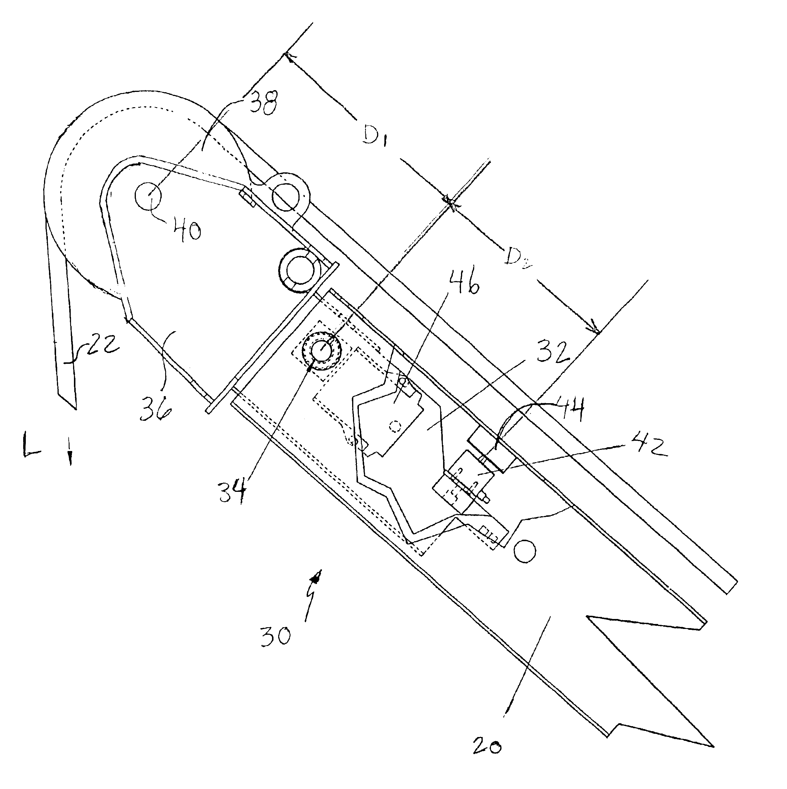
FIG. 1 illustrates the invention, generally designated by reference numeral 30. A device in accordance with the invention is mounted on a jib extension 20, as discussed above with respect to FIG. 4.

The illustration of jib extension 20 is partly broken away to show an insert 32 inserted at the tip of jib extension 20. Insert 32 is pivotally mounted to jib extension 20 at a pivotal mount 34 positioned at a first location. Mount 34 may be, for example, a chrome plated pivot pin supported on extension 20 or any comparable device for permitting the insert to pivot when a force is applied. Alternatively, pin 34 or a similar element could be mounted on insert 32 and extend into apertures associated with jib extension 20.

An extended portion 36 of insert 32 rotationally supports a sheave 38 on a rotational axis 40 positioned at a second location on insert 32. In this embodiment, the second location of axis 40 is displaced from the first location of pivot 34 in a first direction generally par...

second embodiment

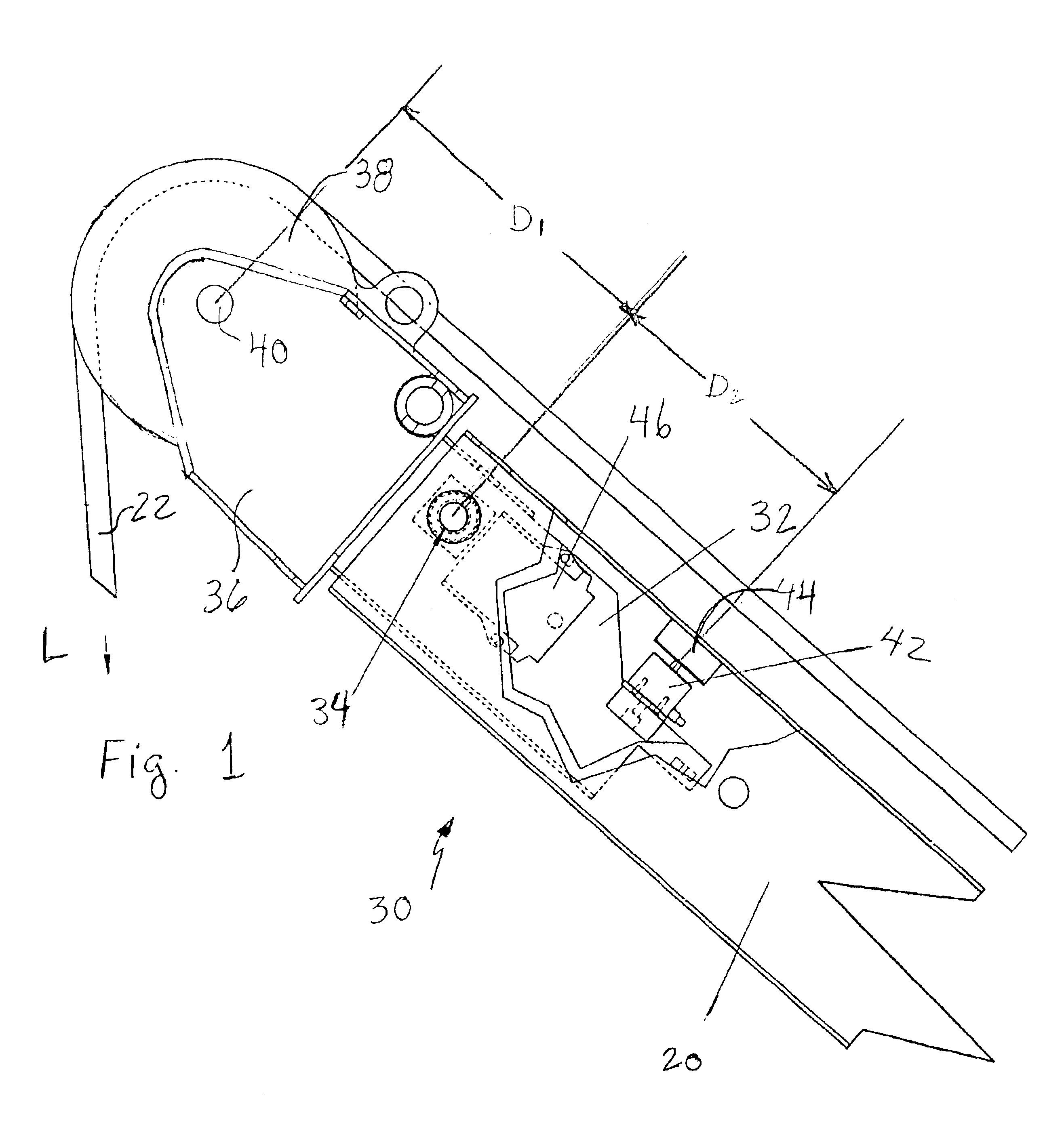
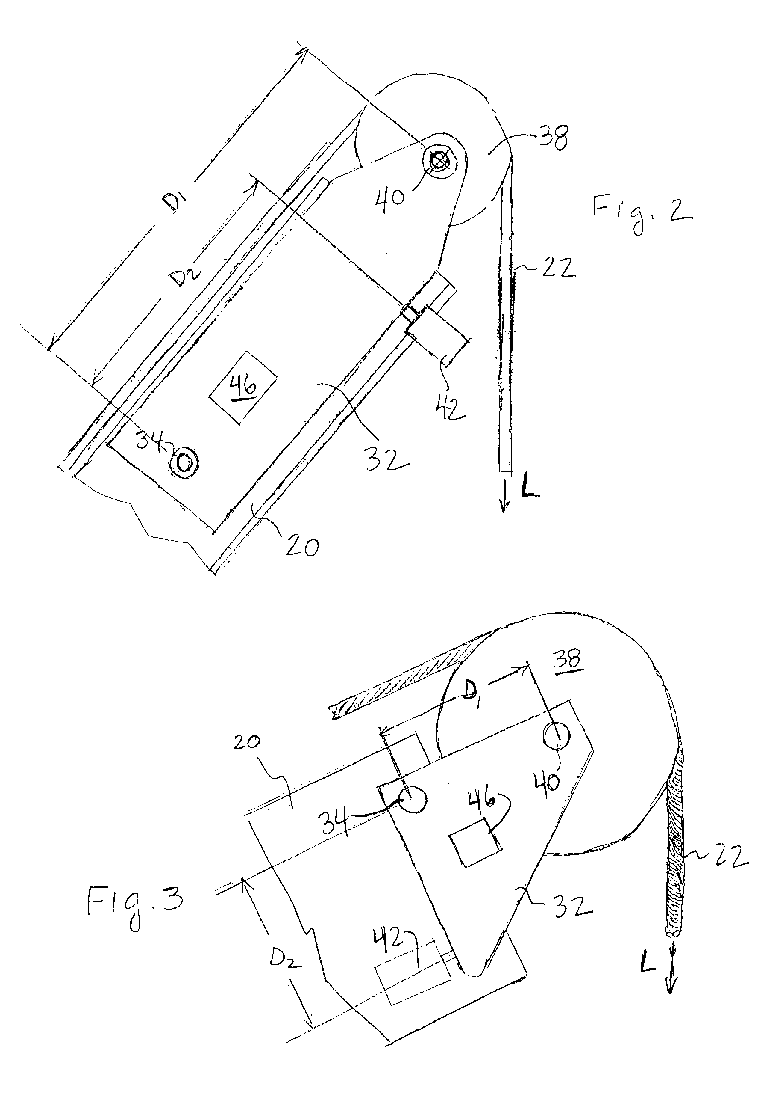
the invention is illustrated in FIG. 2. Elements corresponding to those illustrated in FIG. 1 are indicated with similar reference numerals.

FIG. 2 schematically illustrates the jib extension 20 shown cut away to reveal jib tip insert 32 pivotally mounted to the jib extension at pivotal mount 34. Sheave 38 is rotationally supported on insert 32 at axis 40. Axis 40 is spaced from the location of pivotal mount 34 in a direction generally along the axis of extension 20 at a distance D1.

Load cell 42 is supported on jib extension 20. Load cell 42 is spaced from pivotal mount 34 at a distance D2 in a direction generally parallel to the axis of extension 20. Load cell 42 bears directly against a surface of jib tip insert 32. Alternately, load cell 42 could be mounted on inset 32 and bear against a surface of jib extension 20.

In a manner similar to that discussed with respect to FIG. 1, a load on the crane hook imparts a force L on cable 22 which passes about sheave 38. This imparts a rotati...


PUM


Abstract

A load limiting device for a jib extension includes a pivotal insert adjacent the tip of the jib extension, a cable sheave mounted on the insert, a force measuring device for measuring forces imposed upon the insert by a load on the cable, an angle transducer for measuring the angle of orientation, and means for determining, based upon such force and angle of orientation, the load on the jib extension.

Description

FIELD OF THE INVENTIONThe invention relates to a load limiting device for an apparatus such as a lifting crane. Particularly, the invention relates to a load limiting device for a jib extension for lifting apparatus such as a crane.BACKGROUND OF THE INVENTIONExtensible boom cranes are well known and widely utilized for lifting loads in various situations. Transportable extensible boom cranes are particularly useful in that they may be easily located and relocated to where tasks are to be performed. The present invention relates to a structure for enhancing the safety of operation of extensible boom cranes, transportable or otherwise.By way of background, FIG. 4 illustrates schematically a transportable extensible boom crane in the form of a truck mounted crane. Such an apparatus comprises generally a truck 1 having an extensible boom crane 2 mounted thereon, as is well known. The crane includes, generally, a base portion 3 mounted to the truck frame and an extensible boom. The boom ...

Claims


Application Information

Patent Timeline
Patent Type & Authority Patents(United States)
IPC IPC(8): B66C23/90B66C23/66B66C23/00
CPCB66C23/905B66C23/66
Inventor SCHNEIDER, WILLIAM DENNISFISCHER, MAX
Owner GROVE US LLC
Why Eureka
Try Eureka