Tile saw

a technology of tile saws and saws, which is applied in the field of tile or masonry saws, can solve the problems of limited loss of time, materials and/or profits for users, and limited maximum cutting capacity of such tile saws,

Inactive Publication Date: 2005-01-25
BLACK & DECKER INC
View PDF7 Cites 38 Cited by
  • Summary
  • Abstract
  • Description
  • Claims
  • Application Information

AI Technical Summary

Benefits of technology

In accordance with the present invention, an improved tile saw is employed. The saw comprises a base, a table disposed on the base, a saw unit disposed on the base, a first stationary rail having a first length extending generally along a first direction, the first stationary rail being connected to one of the table and saw unit, and a first movable rail engaging the first stationary rail and extending generally parallel to the first stationary rail, the first movable rail being connected to the other of the table and saw unit, wherein the first movable rail is movable with respect to the first stationary rail such that the other of the table and saw unit is movable generally along the first direction over a range which exceeds the first length. Preferably, the first movable rail is slidingly received over the first stationary rail.

Problems solved by technology

However, the maximum cutting capacity of such tile saws is limited by the size of the machine, i.e., the envelope.
Such tile saws, however, are usually susceptible to dust collecting between the tracks and wheels, which creates binding between the base and the table.
Ultimately, the binding may cause uneven, inaccurate cuts, which may translate into loss of time, materials and / or profit for the user.
Further, the capacity of such tile saws is usually limited to the length of the tracks.
However, longer tracks may result in less portability of the tile saw.

Method used


Image

  • Tile saw
  • Tile saw
  • Tile saw

Examples


Embodiment Construction

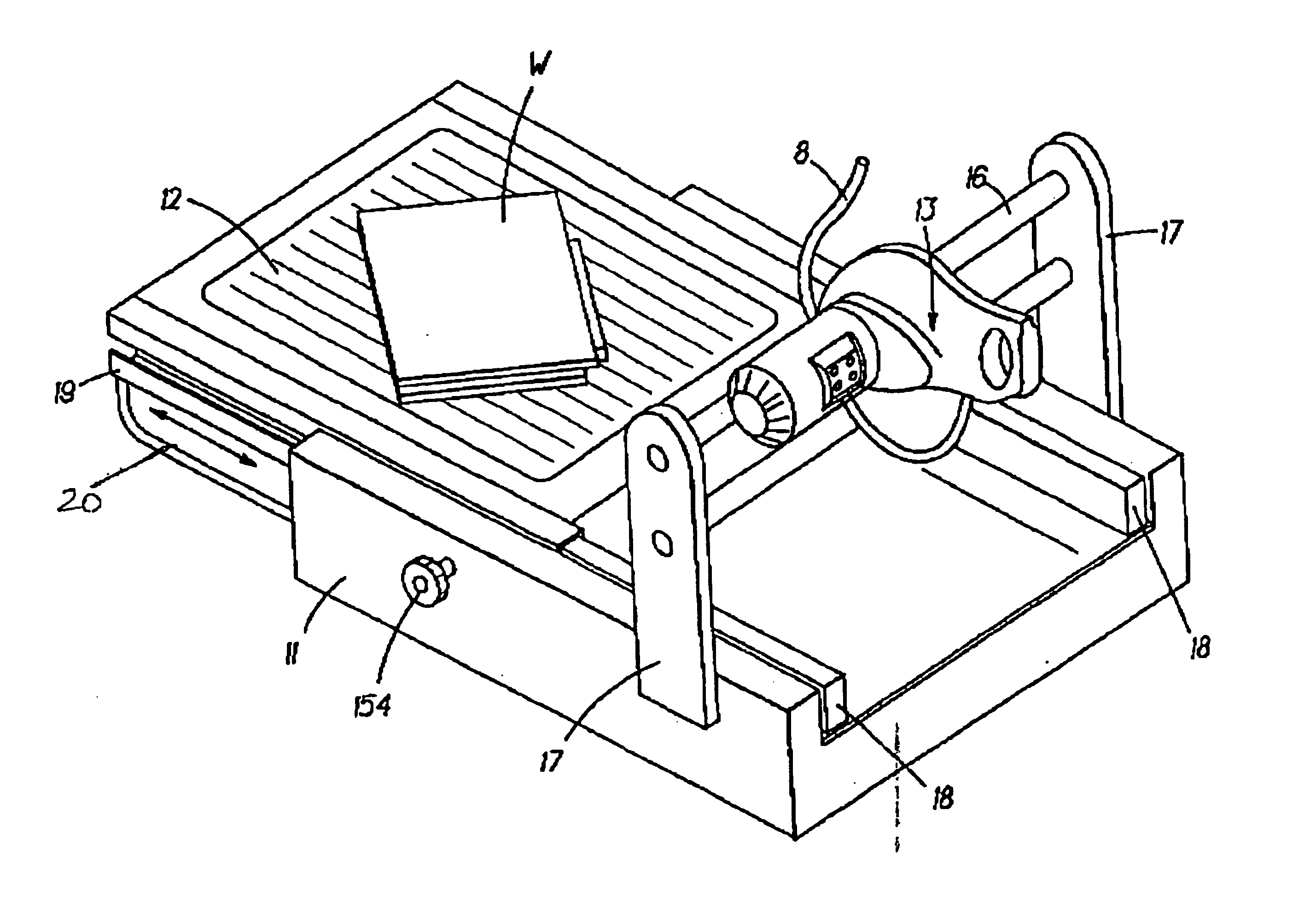
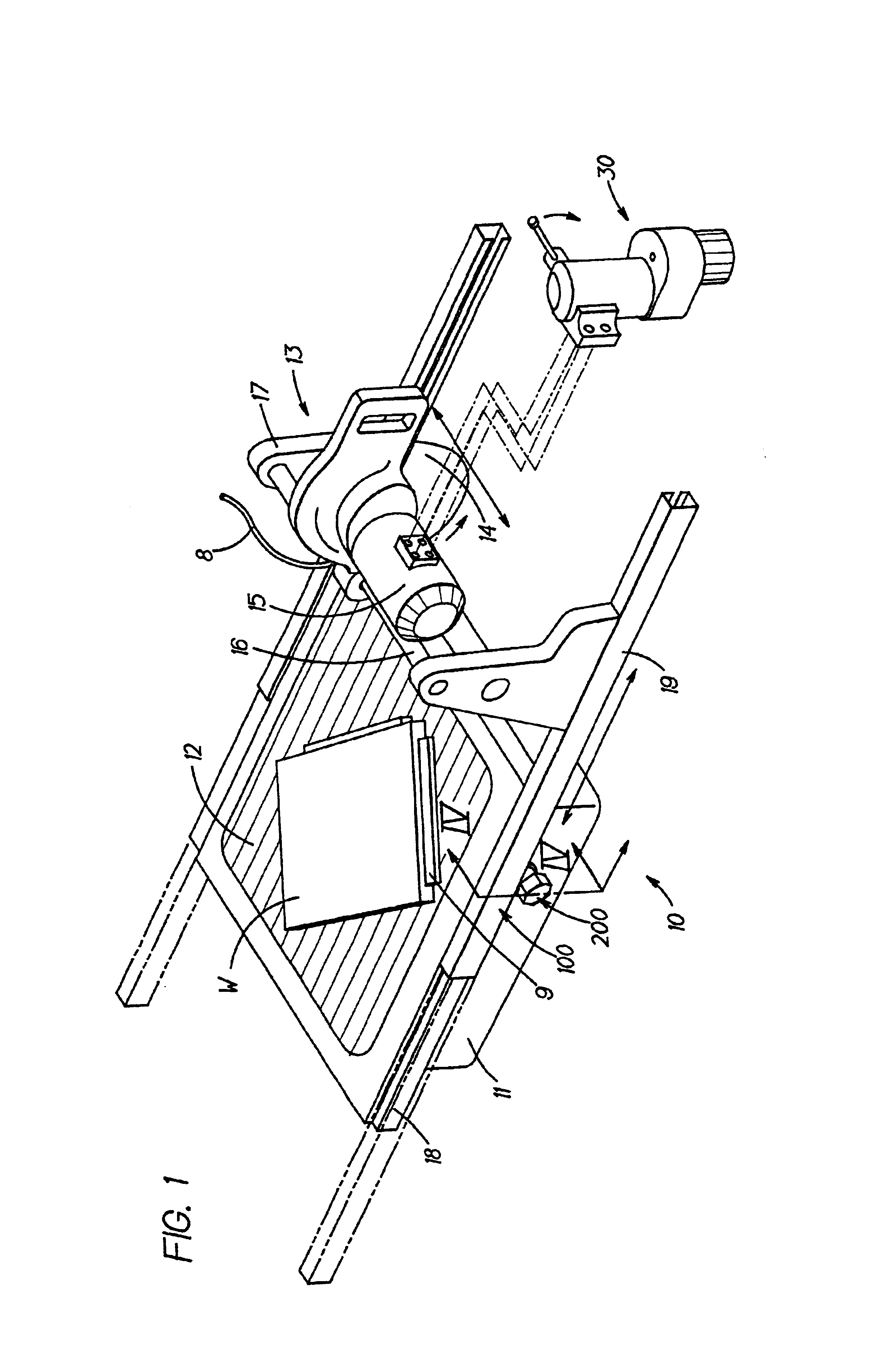
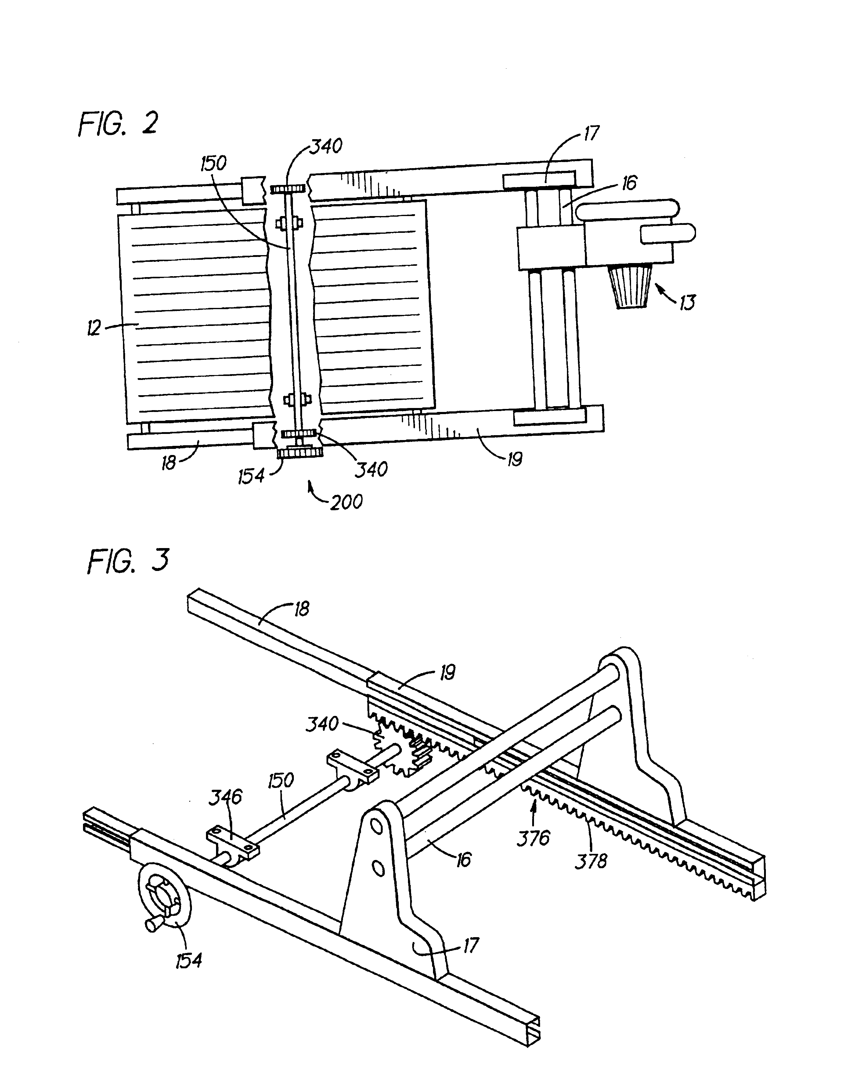
The invention is now described with reference to the accompanying figures, wherein like numerals designate like parts. FIG. 1 illustrates a first embodiment of the present invention, where tile saw 10 comprises a base 11 which supports a generally rectangular work table 12. Slidable relative to table 12 is saw unit 13, which comprises a blade 14 and a motor 15 driving the blade 14. The saw unit 13 is slidably disposed on guide rods 16, so that the saw unit 13 can be positioned at any position along rods 16. Persons skilled in the art will recognize that one guide rod 16 may be used, but it is preferred to use at least two rods 16 in order to maximize stability.

Further, saw unit 13 can be adapted to bevel, i.e., change the angle of blade 14 relative to the table 12, as is known in the art.

Saw unit 13 also has a water conduit 8 for lubricating and cooling the blade 14, as is known in the art. Water sent through conduit 8 will drain into base 11 through table 12 and may be repumped thr...


PUM

PropertyMeasurementUnit
lengthaaaaaaaaaa
sizeaaaaaaaaaa
timeaaaaaaaaaa

Abstract

A saw includes a base having a first length extending generally along a first direction, a table disposed on the base, a saw unit disposed on the base, wherein one of the table and the saw unit is movable relative to the base along the first direction over a range which exceeds the first length. The saw may also include a first stationary rail connected to the base and extending generally along the first direction and a first movable rail engaging the first stationary rail and extending generally parallel to the first stationary rail, the first movable rail being connected to the one of the table and saw unit. Preferably, the first movable rail is slidingly received over the first stationary rail. The saw may also include a first rack disposed on the first movable rail, and a first pinion disposed on the base, wherein the first pinion meshes with the first rack so that the first movable rail moves along the first direction upon rotation of the first pinion. Preferably, the saw further includes a second stationary rail connected tot the base and extending generally along the first direction and substantially parallel to the second stationary rail, and a second movable rail engaging the second stationary rail and extending generally parallel to the first movable and second stationary rails, the second movable rail being connected to the one of the table and saw unit.

Description

FIELD OF THE INVENTIONThis invention relates generally to tile or masonry saws and, more particularly, to tile saws with expanded capacity.BACKGROUND OF THE INVENTIONA typical tile saw includes a base which supports a generally flat table top. A saw unit may be disposed on the base or table for cutting a workpiece, such as a tile or masonry brick, disposed on the table. However, the maximum cutting capacity of such tile saws is limited by the size of the machine, i.e., the envelope.Accordingly, persons skilled in the art have devised a tile saw where the base has two tracks and the table has bearings or wheels riding on the tracks, so that the table can be slid relative to the saw unit for increased capacity. Such tile saws, however, are usually susceptible to dust collecting between the tracks and wheels, which creates binding between the base and the table. Ultimately, the binding may cause uneven, inaccurate cuts, which may translate into loss of time, materials and / or profit for...

Claims


Application Information

Patent Timeline
Patent Type & Authority Patents(United States)
IPC IPC(8): B23D45/02B23D47/02B23D47/00B28D1/04B23D45/00B28D1/02
CPCB23D45/02B23D45/021B23D45/027B28D1/047B28D1/043B28D1/044B23D47/025
Inventor O'BANION, MICHAEL L.PUZIO, DANIELHARDEBECK, JASON D.
Owner BLACK & DECKER INC
Why Eureka
Try Eureka