Machine for cutting parts of a window blind

a cutting machine and window blind technology, applied in the field of window blinds, can solve the problems of increasing the cost, complicated operation procedure, and inability of the cutting machine to produce a good cutting edge at each window blind part, and achieve the effect of simplifying the cutting process and improving the cutting

Inactive Publication Date: 2005-07-14
NIEN MADE ENTERPRISE CO LTD
View PDF17 Cites 28 Cited by
  • Summary
  • Abstract
  • Description
  • Claims
  • Application Information

AI Technical Summary

Benefits of technology

[0010] It is another objective of the present invention to provide a window blind cutting machine, which enhances the cutting effect and simplifies the cutting process by employing two cutters at two ends of the cutting machine for cutting two ends of the window blind.
[0011] It is still another objective to provide a window blind cutting machine, which has an automatically cutting effect.

Problems solved by technology

However, as stated above, this window blind cutting machine cannot produce a good cutting edge at each window blind part.
When two drive sources are used (see FIGS. 2, 7, and 15 of the disclosure), the cost is relatively increased, and the operation procedure is complicated.
When a common drive source is used (see FIG. 8 of the disclosure), the machine is not practical for cutting a window blind having a metal headrail and wooden slats.
Using the aforesaid conventional window blind cutting machines to cut the two ends of the window blind requires much labor since the other end of the window blind to be cut off will be manually set in position for cutting after the one end of the window blind has been cut.

Method used


Image

  • Machine for cutting parts of a window blind
  • Machine for cutting parts of a window blind
  • Machine for cutting parts of a window blind

Examples


Embodiment Construction

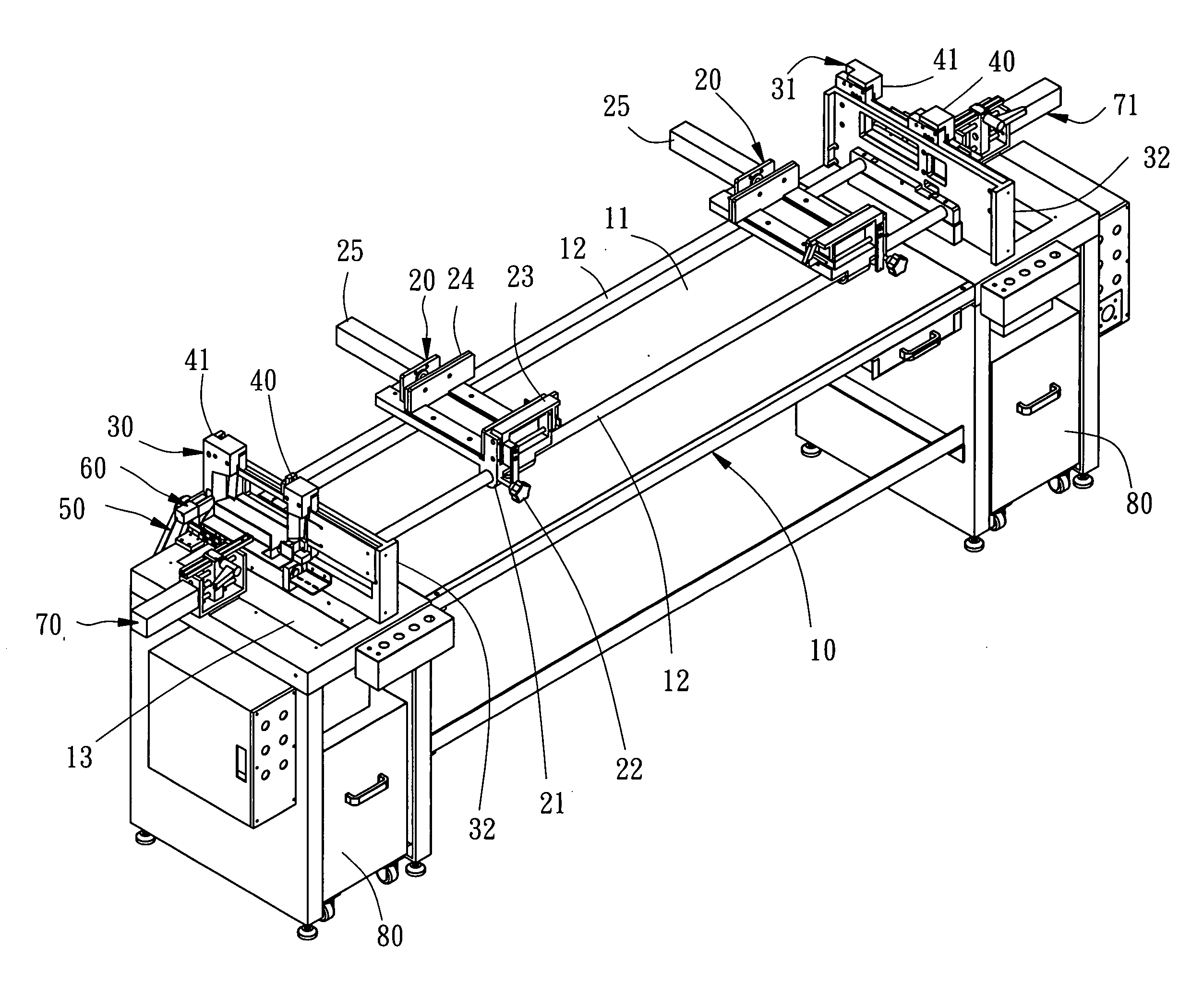
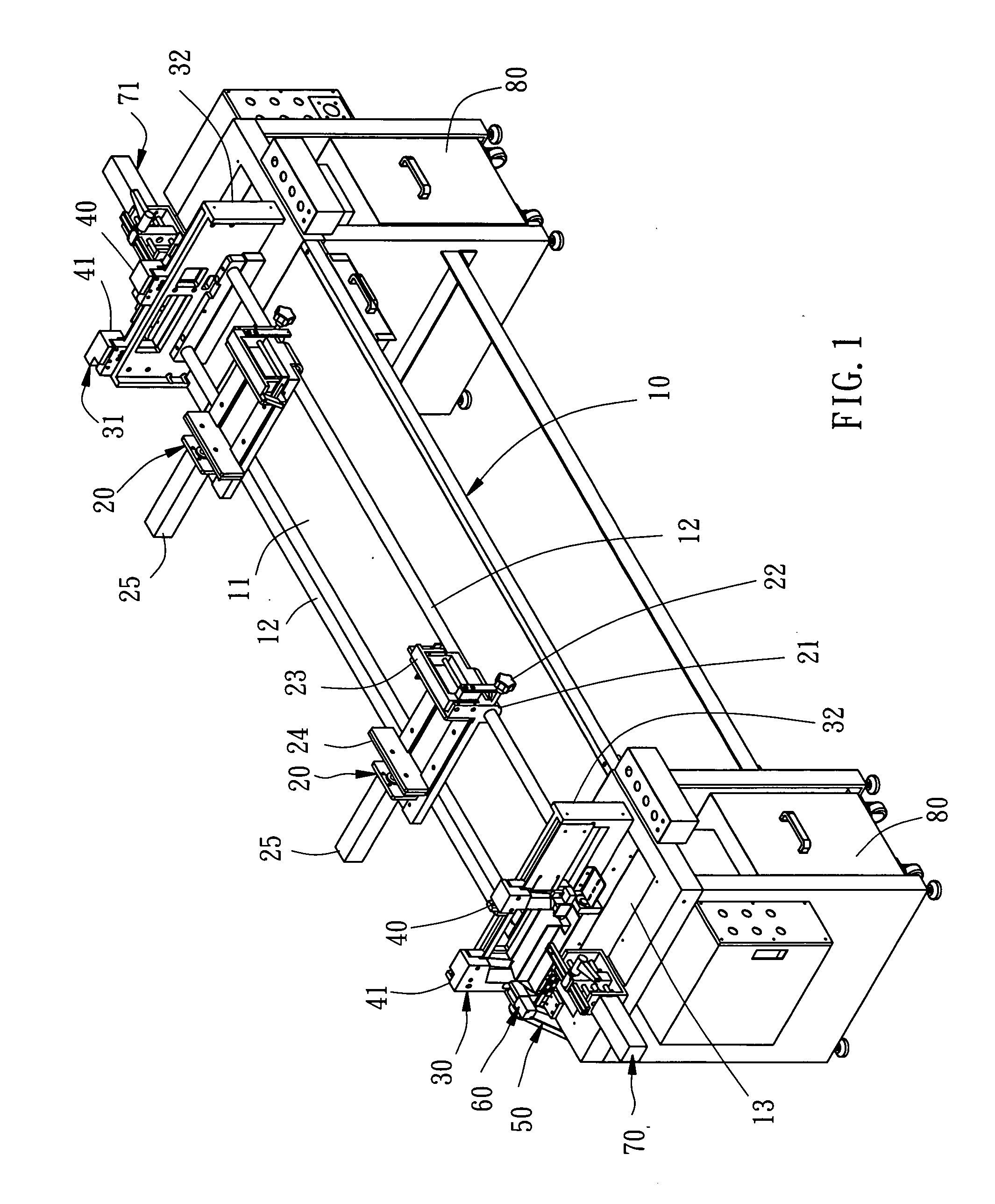
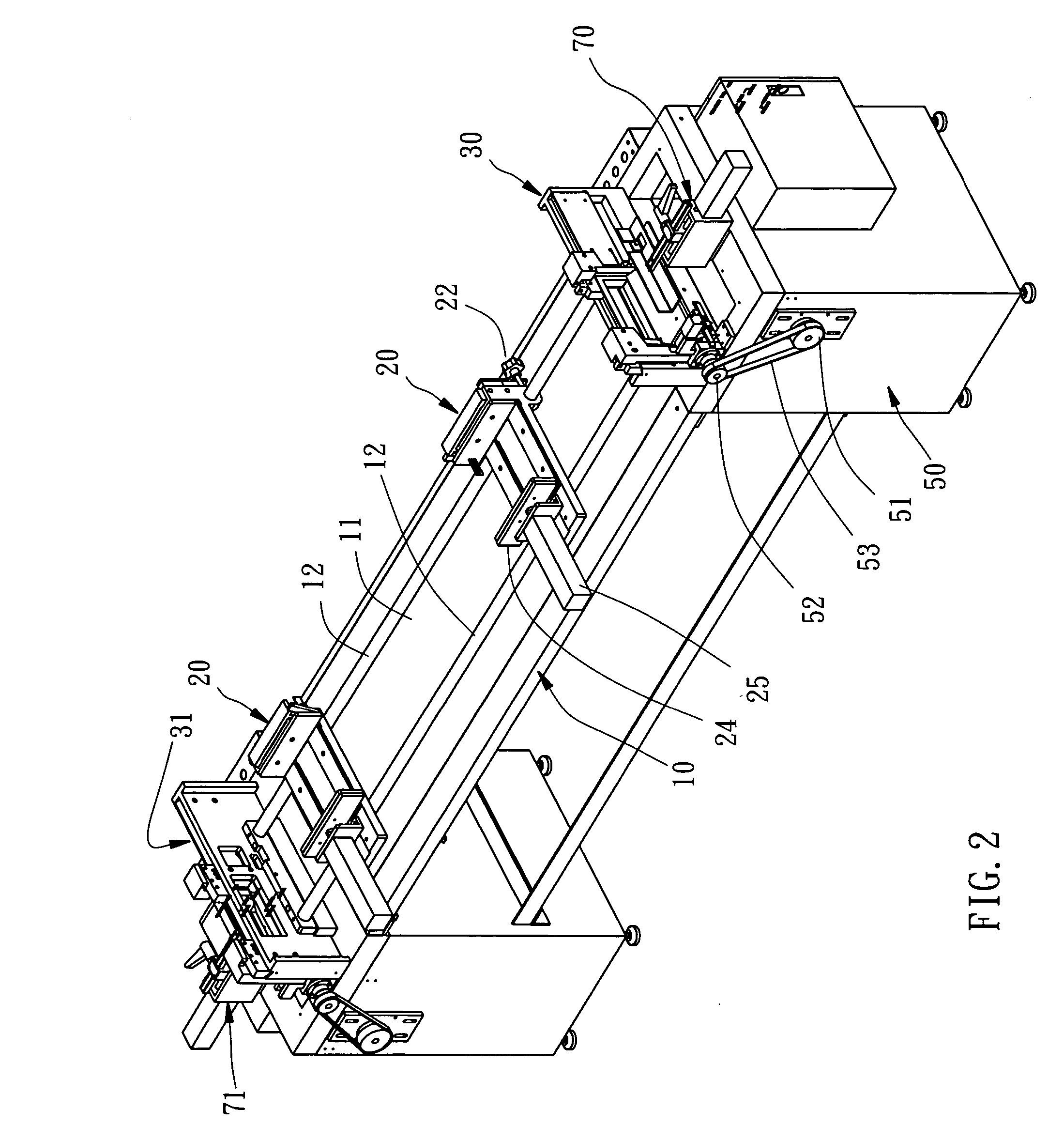
[0020] Referring to FIGS. 1-4, a window blind cutting machine is shown comprising an elongated machine base 10, a first cutting unit 30 and a second cutting unit 31 disposed near the two distal ends of the machine base 10 at the top, two clamping seats 20 mounted on the machine base 10 and respectively slidable on the machine base 10 between the first cutting unit 30 and the second cutting unit 31, a first measuring unit 70 and a second measuring unit 71 respectively disposed at the two distal ends of the machine base 10 adjacent to the cutting units 30 and 31 at an outer side, and two dust baskets 80 respectively mounted in the machine base 10 below the cutting units 30 and 31.

[0021] The machine base 10 has an elongated worktable 11, two guiding rods 12 longitudinally arranged in parallel on the worktable 11, and two top openings 13 disposed near the two distal ends thereof and adapted to guide waste chips to the dust baskets 80 that are respectively disposed below the two top ope...


PUM

PropertyMeasurementUnit
lengthaaaaaaaaaa
sizesaaaaaaaaaa
shapeaaaaaaaaaa

Abstract

A machine for cutting parts of a window blind includes a machine base and two cutting units mounted respectively on the machine base. Each cutting unit includes two locating holes for insertion of the parts of the window blind, two cutters movable relative to the locating holes, a clutch for connecting and disconnecting the cutters, and a driving mechanism. The driving mechanism drives the cutters to move synchronously to cut off the parts of the window blind that extend out of the locating holes when the cutters are connected by the clutch. The driving mechanism drives only one of the cutters to move to cut off the parts of the window blind that extend out of one of the locating holes when the cutters are disconnected.

Description

BACKGROUND OF THE INVENTION [0001] 1. Field of the Invention [0002] The present invention relates generally to window blinds and more specifically, to a cutting machine for cutting parts of a window blind subject to the desired length. [0003] 2. Description of the Related Art [0004] Window blind manufacturers provide only a limited number of sizes for each model, and the retailers or upholsterers cut the window blinds to the desired sizes by means of a window blind cutting machine when selling or installing the window blinds. [0005] The parts of a window blind are generally comprised of a headrail, a set of slats, and a bottom rail. These window blind parts may be made of different materials. For example, the headrail may be made of hard metal, and the slats may be made of aluminum, PVC (polyvinyl chloride), compound material, or wood. Commonly, the bottom rail and the slats are made of same material. Cutting different materials of window blind parts at a time may cause window blind...

Claims


Application Information

Patent Timeline
Patent Type & Authority Applications(United States)
IPC IPC(8): B23D23/00B26D1/00B26D1/09B26D5/08B26D7/01B26D11/00E06B9/266
CPCB26D1/09B26D11/00B26D7/01B26D5/08Y10T83/929
Inventor NIEN, MINGLEE, WEN-YEU
Owner NIEN MADE ENTERPRISE CO LTD
Why Eureka
Try Eureka