Electric hair clipper structure

a technology of electric hair clippers and electric motors, applied in the direction of metal working devices, etc., can solve the problems of hard control of shearing speed and shearing effect or speed, and achieve the effect of better shearing

Inactive Publication Date: 2007-09-20
CHEN CHENG HSIANG +1
View PDF4 Cites 24 Cited by
  • Summary
  • Abstract
  • Description
  • Claims
  • Application Information

AI Technical Summary

Benefits of technology

[0008] When using the above structure, the moving blade continuously makes crossover displacements with the stationary blade. When the gap on the stationary blade corresponds to the gap on the moving blade, a temporary space for holding hair is formed, such that when the barber sets the electric hair clipper into action again, the ha...

Problems solved by technology

However, referring to FIG. 1, when a barber sets a conventional electric hair clipper a into action, and when a cutting edge a1 comes into contact with a longer hair b, the hair b that enters into the cutting edge a1 is sometimes pushed outward along an outline of the cutting edge a1 when ...

Method used


Image

  • Electric hair clipper structure
  • Electric hair clipper structure
  • Electric hair clipper structure

Examples


Embodiment Construction

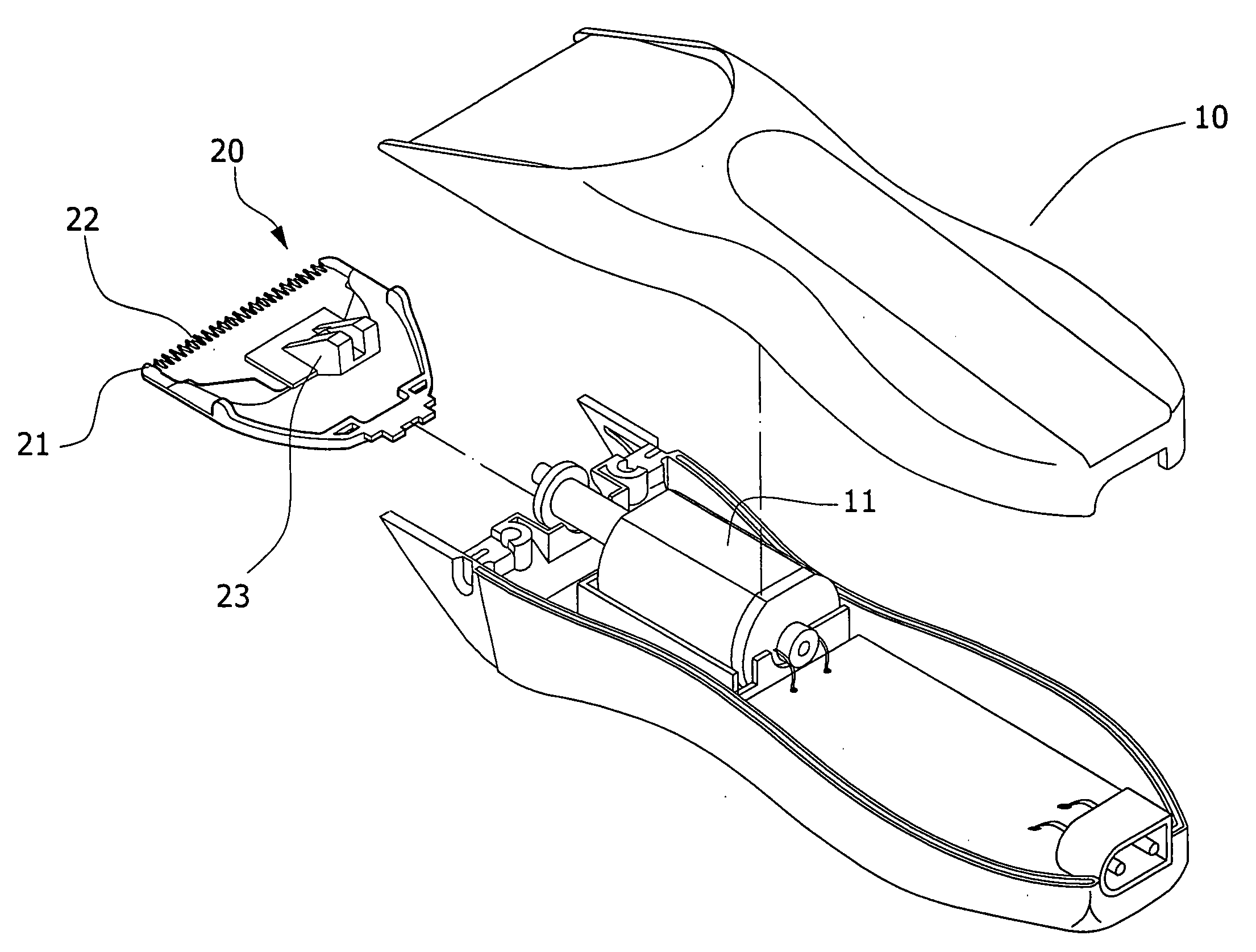
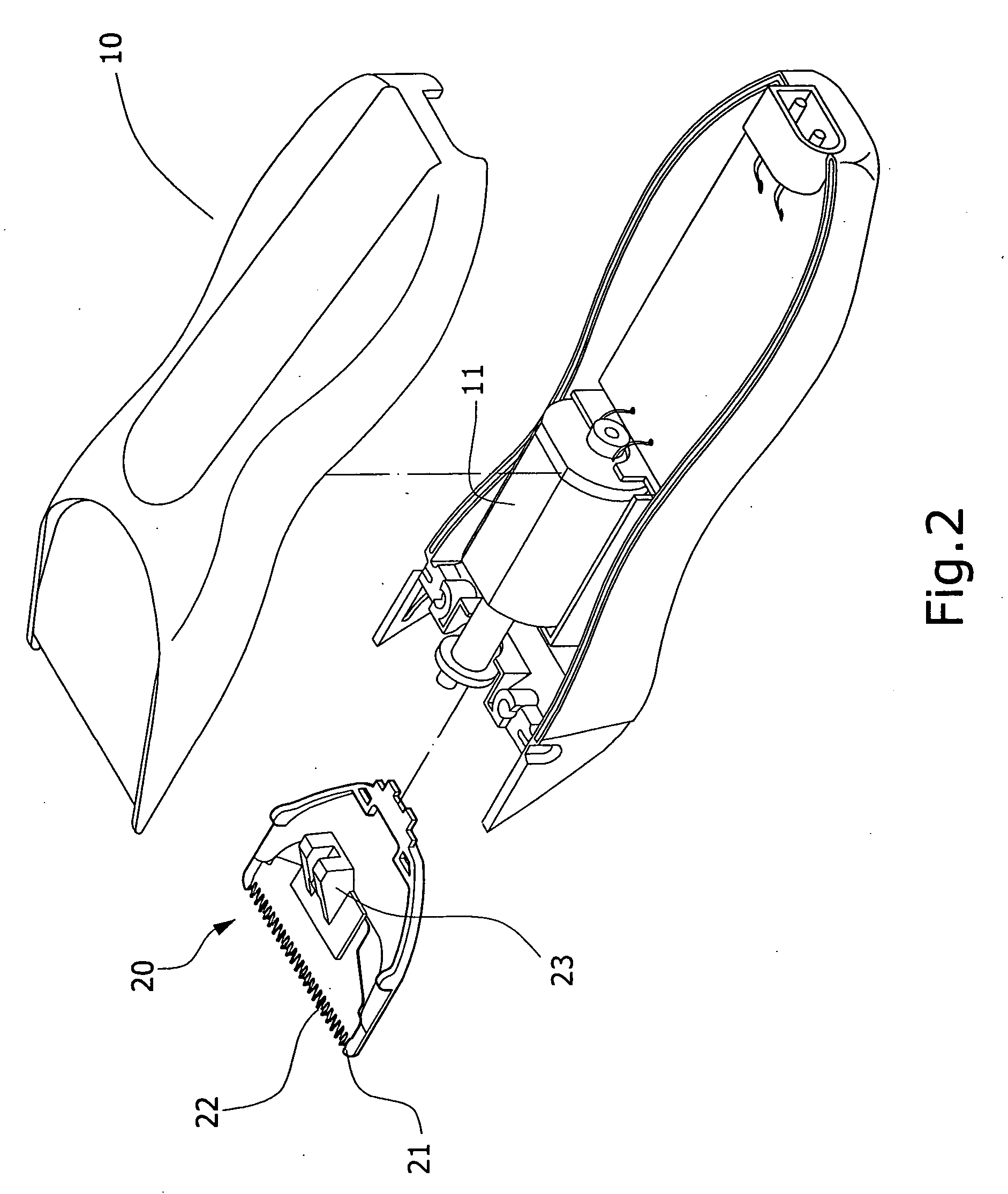
[0017] Referring to FIG. 2 to FIG. 6, the present invention provides a shearing tool set 20 formed on a front end of a housing 10. The shearing tool set 20 comprises a stationary blade 21 and a vibratory base 23 having a moving blade 22, wherein the stationary blade 21 is positioned at a suitable location on an exterior of the vibratory base 23 such that the moving blade 22 forms a superimposed structure on the stationary blade 21. The vibratory base 23 is driven by a motor 11 inside the housing 10 such that the moving blade 22 and the stationary blade 21 form cross-over displacements, wherein triangular saw-tooth cutting edges 21a and 22a are configured at front edges of the stationary blade 21 and the moving blade 22, and continuous gaps 21b and 22b are provided on a suitable location on an internal surface of each saw-tooth on the respective cutting edges 21a and 22a of the stationary blade 21 and the moving blade 22. The gaps 21b and 22b can be in the shape of a semicircle, a tr...


PUM


Abstract

The present invention provides a shearing tool set formed on a front end of a housing. The shearing tool set comprises a stationary blade and a vibratory base having a moving blade, wherein the stationary blade is positioned at a suitable location on an exterior of the vibratory base such that the moving blade forms a superimposed structure on the stationary blade. The vibratory base is driven by motor inside the housing such that the moving blade and the stationary blade form cross-over displacements, and continuous gaps are provided on a suitable location on an internal surface of each saw-tooth on the respective cutting edges of the stationary blade and the moving blade. When the gaps on the stationary blade converge relative to the gaps on the moving blade, a temporary space is formed for holding hair, thereby preventing the hair from sliding during shearing and affecting the shearing effects.

Description

BACKGROUND OF THE INVENTION [0001] (a) Field of the Invention [0002] The present invention relates to an electric hair clipper structure, more particularly, to a shearing tool structure that is capable of reducing the negative impact of hair sliding movements on hair shearing effects. [0003] (b) Description of the Prior Art [0004] Nowadays, the majority of barber shops use electric hair clippers for haircut, especially for cutting longer hair. A suitable shearing tool set is provided on a front end of the majority of electric hair clippers on sale in the market. The shearing tool set comprises a stationary blade and a moving blade, wherein the moving blade is connected to a linkage inside a vibratory base whereas the stationary blade is provided on a suitable location on the vibratory base, such that the moving blade forms a superimposed structure on the stationary blade. Then triangular saw-tooth cutting edges are configured at front edges of the moving blade and the stationary bla...

Claims


Application Information

Patent Timeline
IPC IPC(8): B26B19/02
CPCB26B19/06B26B19/3846
Inventor CHEN, CHENG-HSIANGYANG, YU-HSIA CHEN
Owner CHEN CHENG HSIANG
Why Eureka
Try Eureka