Rotating jet flow polishing device and method

A polishing device and jet technology, which is applied to used abrasive treatment devices, abrasives, metal processing equipment, etc., can solve the problems of low polishing efficiency and small removal function spots, so as to improve polishing efficiency, improve processing quality, and ensure The effect of processing quality

Pending Publication Date: 2020-11-06
TIANJIN UNIV
View PDF0 Cites 0 Cited by
  • Summary
  • Abstract
  • Description
  • Claims
  • Application Information

AI Technical Summary

Problems solved by technology

In addition, the current jet polishing technology has a disadvantage. In order to ensure sufficient pressure when the jet impacts the workpiece, the nozzle diameter is small and the jet beam is very thin, so the removal function spots are small and the polishing efficiency is also very low.

Method used


Image

  • Rotating jet flow polishing device and method
  • Rotating jet flow polishing device and method
  • Rotating jet flow polishing device and method

Examples


Embodiment 1

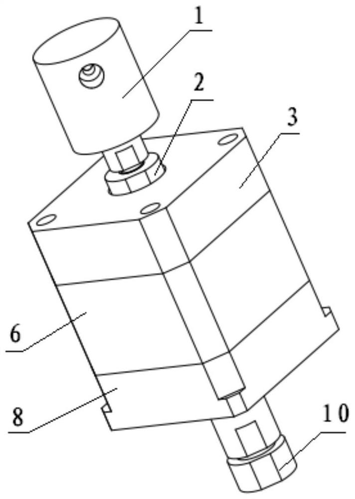
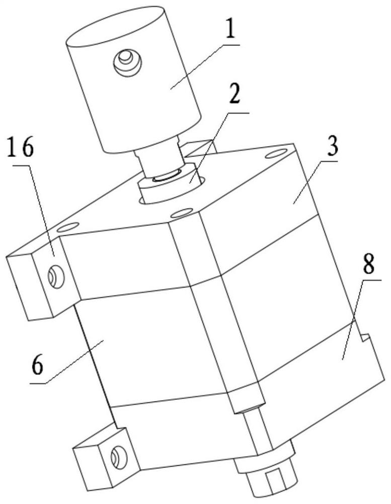
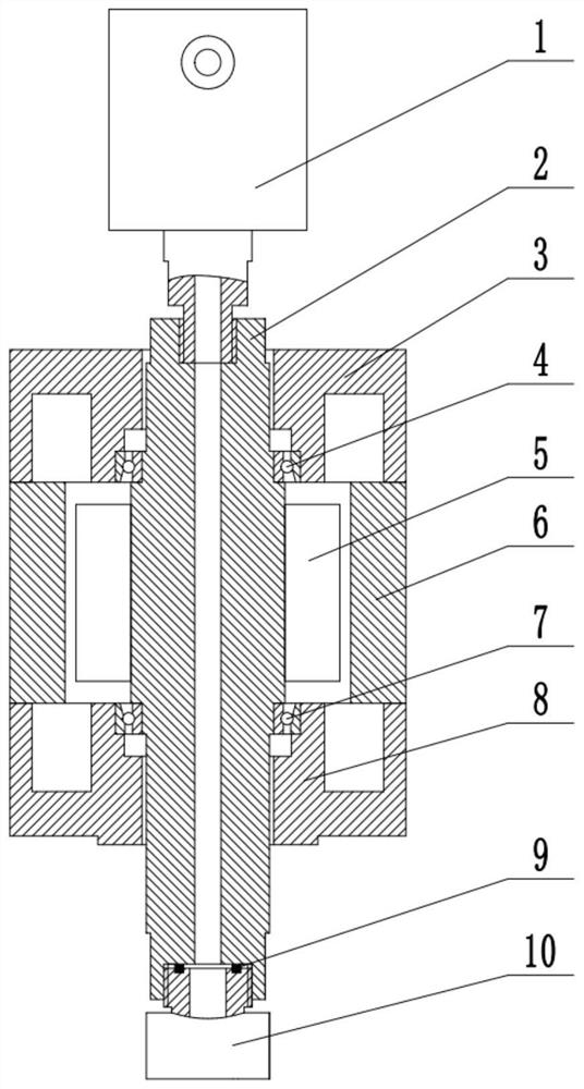
[0060] In this embodiment, the rotary jet nozzle part 15 of the present invention can be installed on the multi-axis motion platform 13, and the motion platform 13 has three degrees of freedom of linear motion of X, Y, and Z and one around the A axis. rotational degrees of freedom, such as Figure 7 As shown, the jet nozzle part 15 is installed on the Z-axis slider of the motion platform 13 through the replacement device 14, and the workpiece to be processed is fixed on the workbench. The jet nozzle part 15 is driven by the Z-axis slider of the moving platform 13 and moved to a suitable position. The liquid supply system 11 transports the polishing liquid to the liquid collection chamber 102 of the polishing nozzle 10 through the liquid supply pipeline, and then passes through the jet nozzle hole 103 is sprayed onto the surface of the workpiece, and the polishing liquid jet rotates around its removal spots to form a Gaussian removal function. Through the rotational speed cont...

Embodiment 2

[0062] In this embodiment, the jet nozzle part 15 of the present invention can be installed on the mechanical arm of an industrial robot. As the end effector of the industrial robot, the rotating nozzle can adjust the distance between the nozzle and the surface of the workpiece and the relative posture of the nozzle and the workpiece by controlling the movement of the mechanical arm. When polishing the workpiece, it is necessary to plan the movement trajectory of the mechanical arm in advance and generate the CNC machining program. The liquid supply system delivers the polishing liquid to the rotating nozzle through the liquid supply pipeline. Driven by the mechanical arm, it is sprayed onto the surface of the workpiece, which can be used for complex curved surfaces. for polishing.


PUM


Abstract

The invention discloses a rotating jet flow polishing device. The device comprises a jet flow nozzle component; the jet flow nozzle component comprises a rotating joint, a rotating main shaft, a polishing nozzle, and a penetrating type motor; the rotating main shaft is a hollow shaft; two ends of the main shaft are respectively connected with an output end of the rotating joint and the polishing nozzle; the penetrating type motor comprises a hollow rotator and a stator; and when the hollow rotator rotates, the rotating main shaft drives the polishing nozzle to rotate. In the process of polishing processing, the jet flow nozzle component is first installed on a movement platform or on a mechanical arm of an industrial robot, a liquid supply system passes a liquid supply pipeline, an input end and an output end of the jet flow nozzle, and a hollow inner cavity of the rotating main shaft successively, and finally polishing liquid reaches the polishing nozzle and is jetted to the surface of a workpiece at certain pressure and speed. The device and method can reduce high frequency errors generated in jet flow polishing, ensure that a removing function formed by jet flow impact on the surface of the workpiece is a Gaussian like function which is symmetrical in a revolving mode and realizes the largest central removal amount, and at the same time improve the efficiency of jet flow polishing.

Description

technical field [0001] The invention relates to a surface polishing processing device and method, and a rotary jet polishing device and method. Background technique [0002] With the development of modern optical industry and optical technology, aspheric optical elements are widely used in advanced optical telephoto, high-sensitivity sensing and high-resolution imaging due to their excellent optical properties. The demand for high-performance and high-quality complex-shaped optical components is constantly increasing, which requires more and more processing equipment and processing technology for complex-shaped parts. At present, there are many polishing methods for complex surface devices, such as abrasive water jet polishing, but the existing technologies have many deficiencies. When the jet is vertically incident, in the stagnation point area of ​​the jet impact, although the impact pressure of the polishing liquid jet is very high, due to the sharp change of the jet vel...

Claims


Application Information

Patent Timeline
Patent Type & Authority Applications(China)
IPC IPC(8): B24C1/08B24C9/00
CPCB24C1/08B24C9/00
Inventor 曹中臣闫升亲李世鹏
Owner TIANJIN UNIV
Why Eureka
Try Eureka