Accurate alignment method for large aperture mirror machine tool

A technology for large-diameter mirrors and processing machine tools, which is applied to metal processing equipment, parts of grinding machine tools, grinding machines, etc. It can solve the problems of low accuracy of alignment methods, optimize the allocation of manpower and equipment resources, and reduce the high frequency of mirror surfaces The effect of improving error and machining convergence efficiency

Active Publication Date: 2013-11-13
CHANGCHUN INST OF OPTICS FINE MECHANICS & PHYSICS CHINESE ACAD OF SCI
View PDF8 Cites 16 Cited by
  • Summary
  • Abstract
  • Description
  • Claims
  • Application Information

AI Technical Summary

Problems solved by technology

[0005] In order to solve the problem of low precision of the mechanical alignment method of large-diameter mirror processing machine tools in optical processing in the prior art, the present invention provides an accurate alignment method for large-diameter mirror processing machine tools. The real-time image acquisition system fixedly connected with the detection probe shoots the characteristic target on the mirror body to be processed, and the host computer calculates the relative rotation angle and translation between the processing grinding head and the mirror body, as well as between the detection probe and the mirror body according to the captured image , to guide the two-dimensional alignment of the CNC machine tool

Method used


Image

  • Accurate alignment method for large aperture mirror machine tool
  • Accurate alignment method for large aperture mirror machine tool
  • Accurate alignment method for large aperture mirror machine tool

Examples


Embodiment Construction

[0040] The present invention will be described in further detail below in conjunction with the accompanying drawings.

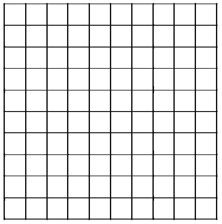
[0041] Such as figure 1 Shown is a schematic diagram of the grid target used for distortion calibration in the present invention. The relative offset between the current position and the reference position calculated by using the image is in units of pixels, and needs to be converted into physical coordinates in mm in the object space to guide the movement of the processing machine tool. Therefore, on the one hand, it is necessary to The system performs magnification calibration, and on the other hand, it is also necessary to correct the change in the corresponding relationship between objects and images in different fields of view caused by the distortion of the imaging lens. The present invention uses a standard grid target for distortion calibration: the actual physical size of the grid target in the object space is known, and the coordinates of each grid i...


PUM


Abstract

The invention discloses an accurate alignment method for a large aperture mirror machine tool, belongs to the technical field of optical machining and detection, and aims to solve the problem of low alignment accuracy in the prior art. The method comprises the following steps of fixedly connecting two sets of image acquisition systems to a machining grinding head and a detection probe of the machine tool respectively; calibrating the distortion of the image acquisition systems; and shooting large and small dot pair targets which are adhered to a non-working area of a mirror body to be machined, comparing large and small dot coordinate change of target images at the current position and the initial reference position, calculating the relative rotation angle and translation quantity of the two positions, repeating the steps, and obtaining surface shape detection distribution of the mirror body after the mirror body is traversed to guide the accurate alignment of the machine tool. The high alignment accuracy between the machining grinding head and the detection probe of the machine tool and the mirror body to be machined provides guarantee for high consistency of the traversing track of the machining grinding head and a machining track planned according to the detection surface shape, and the surface shape with higher machining accuracy can be obtained.

Description

technical field [0001] The invention relates to an alignment method for a large-diameter mirror processing machine tool, and belongs to the technical field of optical processing and detection. Background technique [0002] Large-aperture optical systems have the characteristics of high spatial angle resolution and strong energy collection capabilities, and are widely used in deep space exploration and high-precision ground imaging. In a large-aperture optical system, the large-aperture aspheric primary mirror is the core component. The aperture and focal length of the primary mirror determine the size and weight of the system. The surface accuracy of the primary mirror is the most important factor for the system to collect high-definition images. One of the prerequisites. [0003] The current optical mirror processing technology mainly includes computer surface forming technology using small grinding head, magnetorheological technology and ion beam technology, as well as st...

Claims


Application Information

Patent Timeline
Patent Type & Authority Applications(China)
IPC IPC(8): B24B13/00B24B49/12
Inventor 陶小平罗霄薛栋林郑立功张学军
Owner CHANGCHUN INST OF OPTICS FINE MECHANICS & PHYSICS CHINESE ACAD OF SCI
Why Eureka
Try Eureka