Multiple tank circulating fuel system

a fuel system and fuel tank technology, applied in water supply installation, valve operating means/release devices, transportation items, etc., can solve the problems of fuel starvation, unrealistic equal fuel draw and return, and engine consumption of fuel

Inactive Publication Date: 2005-01-25
INT TRUCK INTPROP LLC
View PDF16 Cites 41 Cited by
  • Summary
  • Abstract
  • Description
  • Claims
  • Application Information

AI Technical Summary

Benefits of technology

In the method of the present invention, the level of fuel in each tank is balanced by detecting the level of fuel in the tank, and then restricting the flow

Problems solved by technology

The engine consumes some of the fuel.
Geometric or mechanical layout differences in tank, draw conduit, and return conduit, or changes in grade during vehicle operation make equal fuel draw and return practically unrealistic.
Premature depletion of fuel in a tank relative to o

Method used


Image

  • Multiple tank circulating fuel system
  • Multiple tank circulating fuel system
  • Multiple tank circulating fuel system

Examples


Embodiment Construction

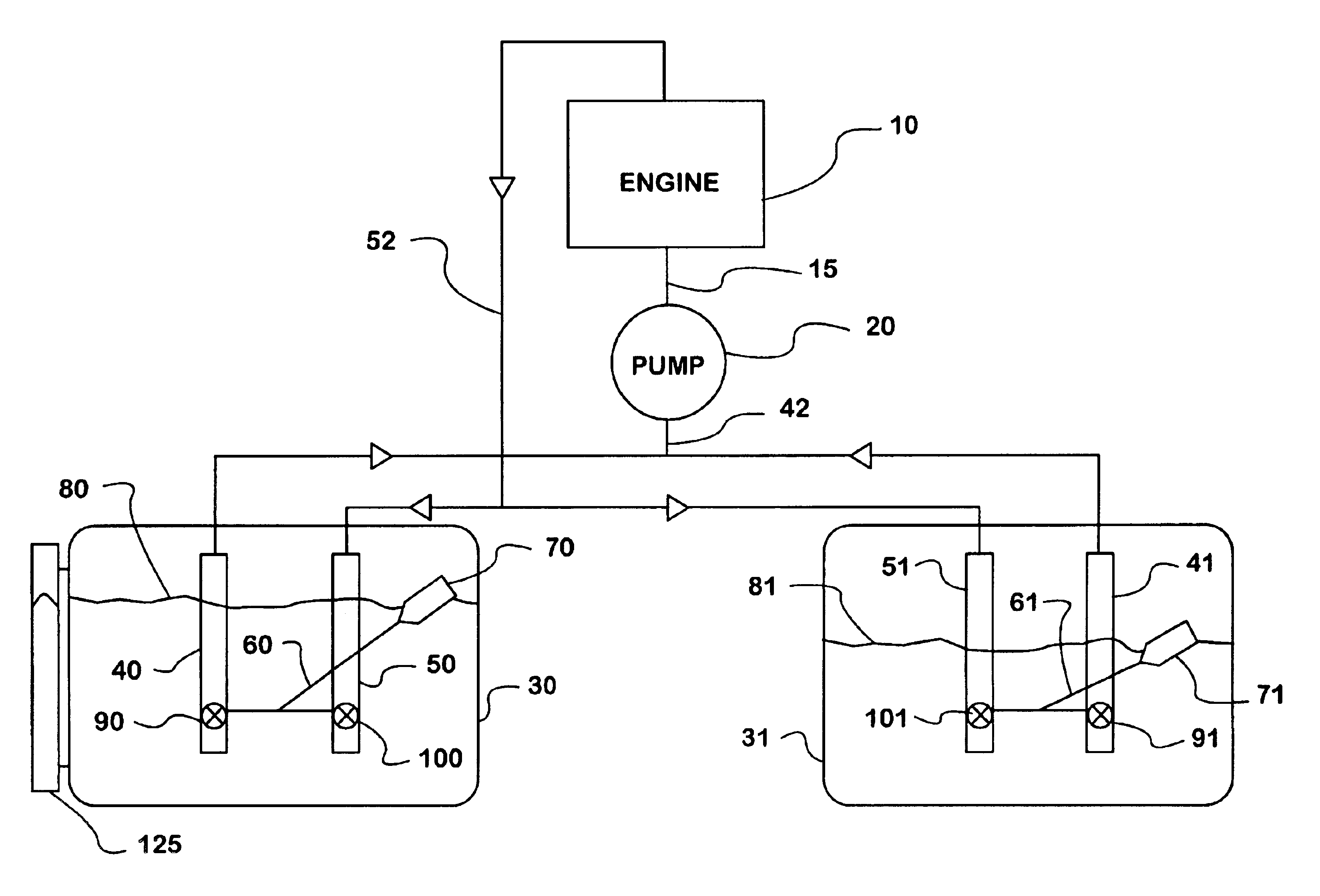
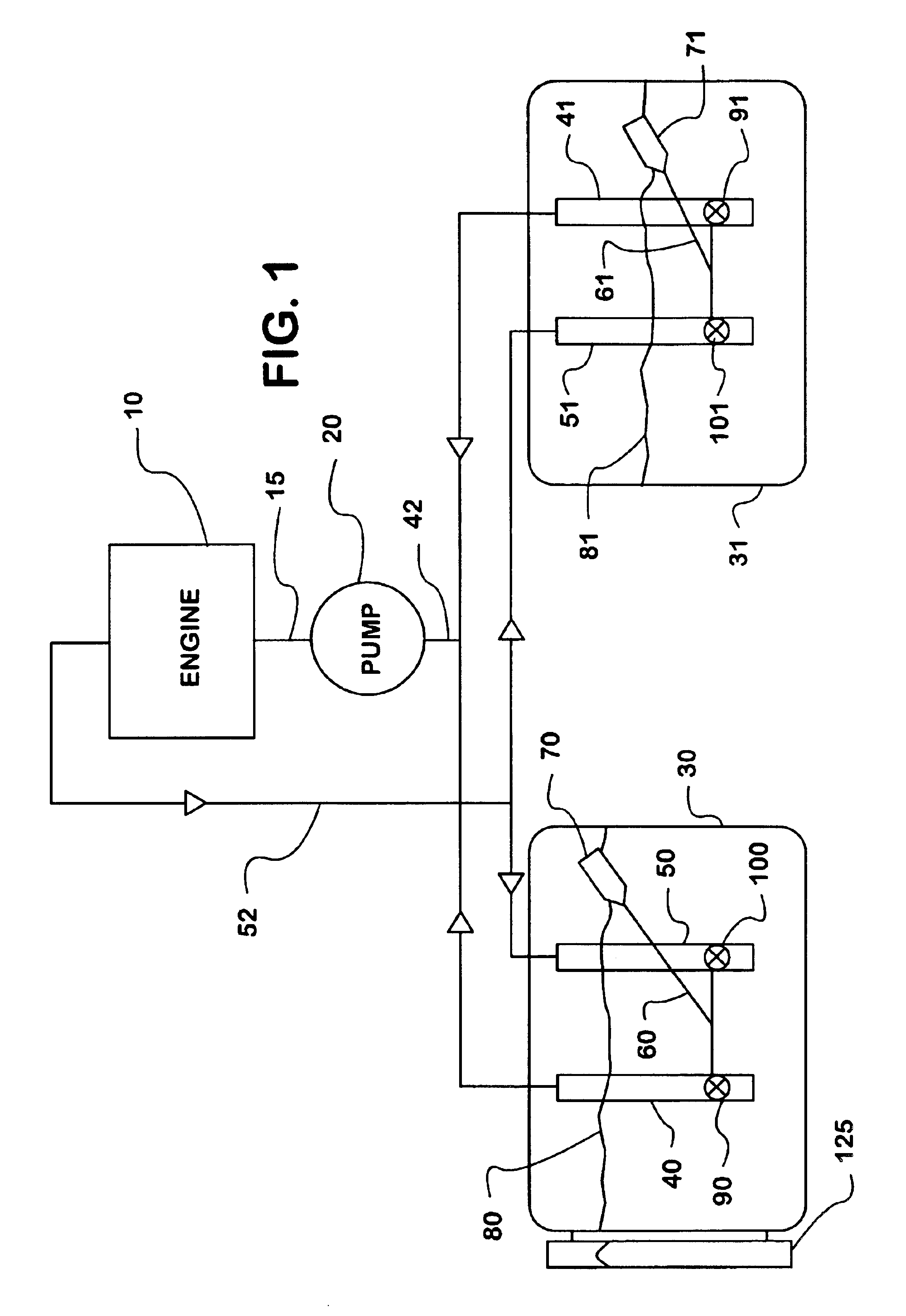
The present invention uses flow restriction devices attached to both the draw and the return conduits of individual fuel tanks to balance the quantity of fuel in the fuel tanks of a circulating fuel system. The explanation of this invention begins with a description of the circulating fuel system with multiple fuel tanks. As shown in FIG. 1, a typical circulating fuel system includes a first tank 30 and a second tank 31. The first and second tanks 30 and 31 contain draw conduits 40 and 41, respectively. The draw conduits 40 and 41 combine into an inlet 42 of the fuel pump 20. The fuel pump discharge 15 connects the fuel pump 20 to the engine 10. In a typical engine the fuel flows through a fuel rail (not shown). A fuel conduit 52 connected to the engine 10 splits into return conduits 50 and 51 which in turn are connected to tanks 30 and 31, respectively.

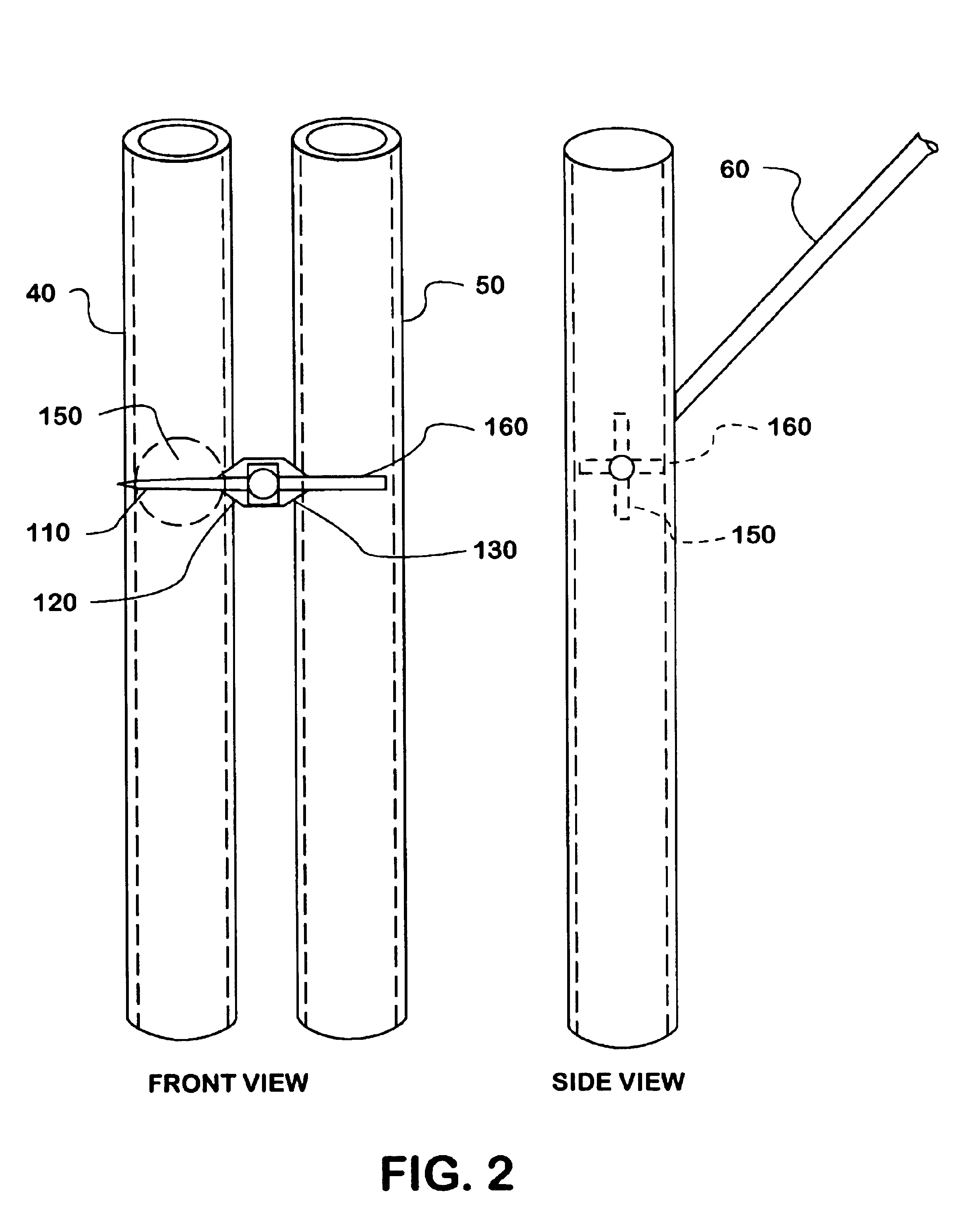
The draw conduit 40 in the first tank 30 contains a draw restriction device 90. Similarly, the return conduit 50 in the first tank ...


PUM


Abstract

An apparatus and method for the balancing of fuel among tanks in a circulating fuel system. The tanks in the system have both a draw conduit and a return conduit mounted to and extending into the tank. Flow restriction devices are mounted in both the draw and the return conduits and are controlled by a fuel level detection system, which detects the fuel in the tank.

Description

BACKGROUND OF INVENTIONThe present invention relates to the balancing of fuel among tanks in a circulating fuel system mounted on a vehicle or other fuel consuming systems with multiple tanks. More specifically flow restriction devices on the fuel flow out of and into each tank are used to balance stored fuel among a number of tanks. The level of fuel in a tank controls the flow restriction devices.PRIOR ARTCirculating fuel supply systems that include multiple fuel tanks are known and are typically used with vehicles. When applied to a vehicle the typical circulating fuel system includes at least two fuel tanks, a fuel pump, and an engine with a fuel supply rail. In operation, the fuel pump draws fuel from the tanks, and pumps the fuel to the fuel supply rail of the engine. The engine consumes some of the fuel. Unconsumed fuel leaves the engine and is returned to the fuel tanks. Thus, fuel is in constant circulation out of and back into the fuel tanks.As typically used with vehicles...

Claims


Application Information

Patent Timeline
IPC IPC(8): B60K15/077
CPCB60K15/077B60Y2200/14B60K2015/03217B60K2015/03144B60K2015/03138B60K2015/03118B60K2015/0348B60K15/03B60K2015/03125Y10T137/7323Y10T137/0318Y10T137/6855Y10T137/7303Y10T137/4673Y10T137/7358
Inventor OSTERKIL, ALAN D.STUART, JOHN W.
Owner INT TRUCK INTPROP LLC
Why Eureka
Try Eureka