High fidelity integrated heat transfer and clearance in component-level dynamic turbine system control

a dynamic turbine and component-level technology, applied in the direction of ratio control, turbine/propulsion engine cooling, liquid fuel engine components, etc., can solve the problems of unstable, unstable flow parameter models, and inability to meet the requirements of the system

Active Publication Date: 2011-03-03
RTX CORP
View PDF93 Cites 185 Cited by
  • Summary
  • Abstract
  • Description
  • Claims
  • Application Information

AI Technical Summary

Benefits of technology

[0008]This invention concerns a control system for a rotary apparatus such as compressor or a turbine, or for a gas turbine engine such as a turbofan. The rotary apparatus comprises a rotor and a housing, which form a gas path through the turbine. The control system comprises a processor and a control law for controlling flow along the gas path.

Problems solved by technology

Existing flow parameter models, on the other hand, are often unstable under low-flow and choked-flow conditions.

Method used


Image

  • High fidelity integrated heat transfer and clearance in component-level dynamic turbine system control
  • High fidelity integrated heat transfer and clearance in component-level dynamic turbine system control
  • High fidelity integrated heat transfer and clearance in component-level dynamic turbine system control

Examples


Embodiment Construction

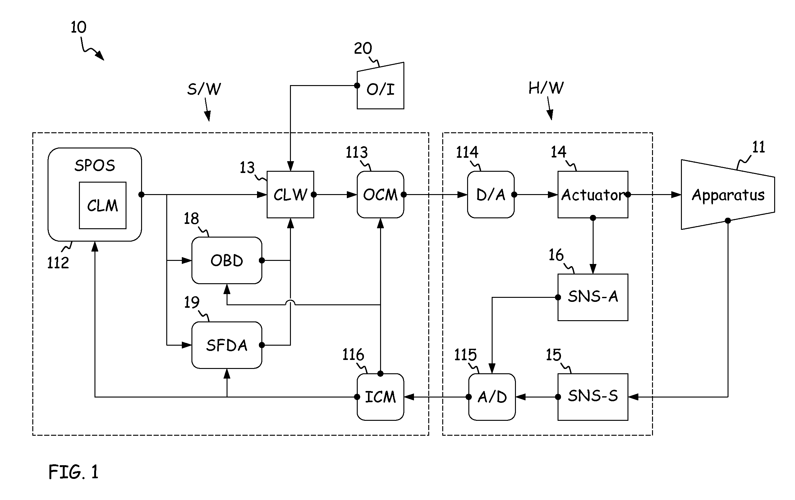
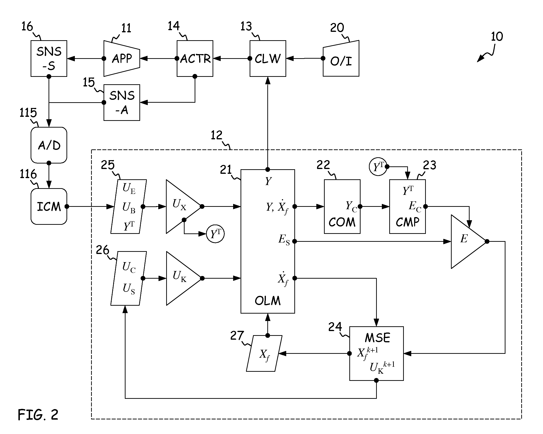
[0022]FIG. 1 is a schematic diagram of digital control system 10 for apparatus 11. Control demands for apparatus 11 are generated by operator interface (I / F) 20, and satisfied by utilizing the components of system 10 to control apparatus (or engineering system) 11.

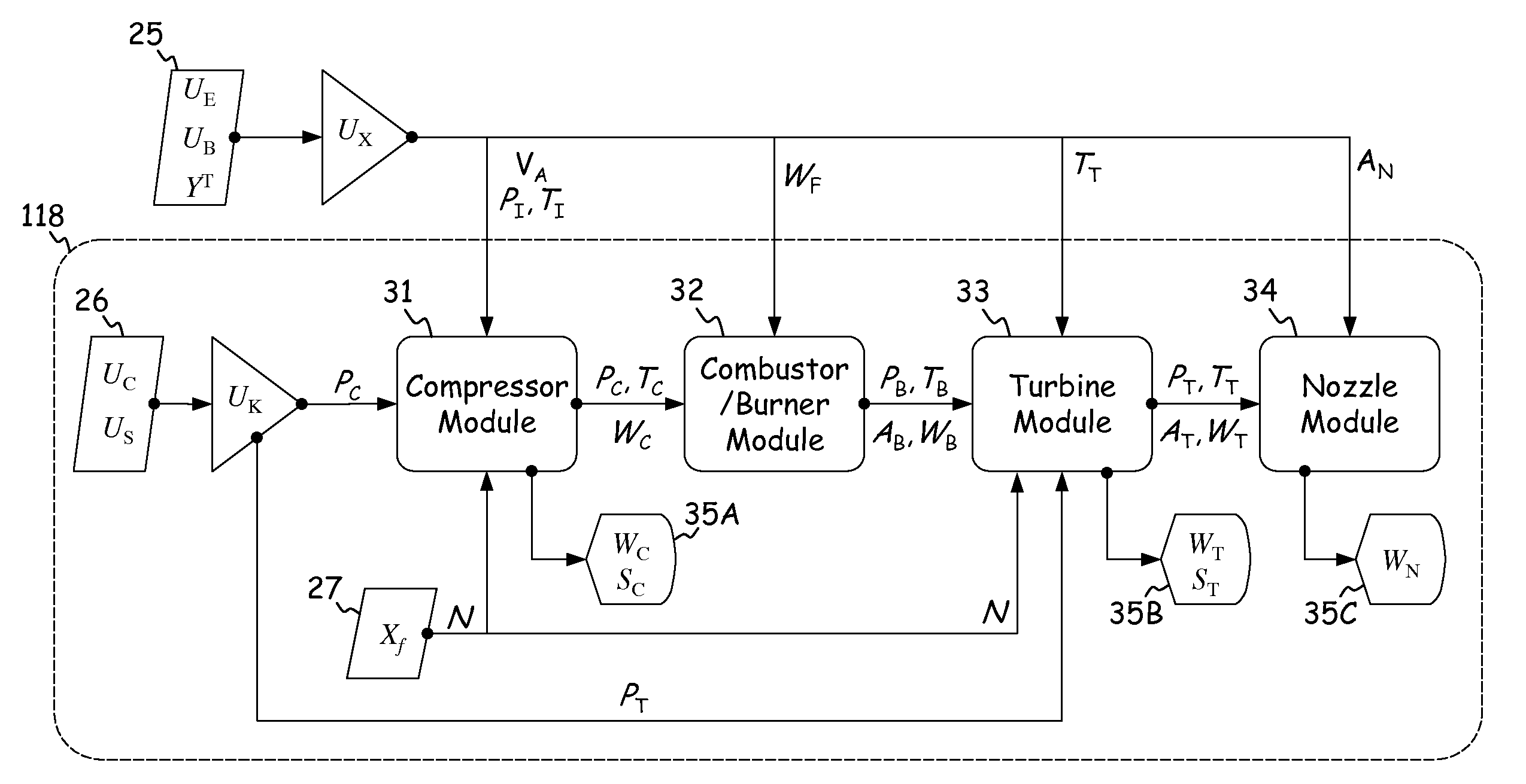
[0023]In general, system 10 includes at least some of the following software (S / W) modules: system parameter on-board synthesis (SPOS) module 112, control law (CLW) 13, on-board diagnostics (OBD) module 18, sensor fault detection and accommodation (SFDA) module 19, output conditioning module (OCM) 113, and input conditioning module (ICM) 116. These modules are incorporated in a “black box” type processor assembly mounted proximate apparatus 11, or in a number of individual processors. SPOS 112 is build around a component-level mathematical model of apparatus 11, also referred to as closed loop model (CLM) 12, such that CLM 12 is a subset of SPOS 112. System 10 also incorporates at least some of the following hardware (H / W)...


PUM


Abstract

A system comprises a rotary apparatus, a control law and a processor. The rotary apparatus comprises a rotor and a housing forming a gas path therebetween, and the control law controls flow along the gas path. The processor comprises an output module, a plurality of temperature modules, a thermodynamic module, a comparator and an estimator. The output module generates an output signal as a function of a plurality of rotor and housing temperatures defined along the gas path, and the temperature modules determine time derivatives of the rotor and housing temperatures. The thermodynamic module models boundary conditions for the gas path, and the comparator determines errors in the boundary conditions. The estimator estimates the rotor and housing temperatures based on the time derivatives, such that the errors are minimized and the flow is controlled.

Description

CROSS-REFERENCE TO RELATED APPLICATION[0001]This application is related to Boris Karpman et al., SYSTEM AND METHOD FOR DESIGN AND CONTROL OF ENGINEERING SYSTEMS UTILIZING COMPONENT-LEVEL DYNAMIC MATHEMATICAL MODEL, Ser. No. 12 / 264,014, filed Nov. 3, 2008. This application is also related to Boris Karpman et al., DESIGN AND CONTROL OF ENGINEERING SYSTEMS UTILIZING COMPONENT-LEVEL DYNAMIC MATHEMATICAL MODEL WITH MULTIPLE-INPUT MULTIPLE-OUTPUT ESTIMATOR, Ser. No. 12 / 475,020, and Boris Karpman et al., DESIGN AND CONTROL OF ENGINEERING SYSTEMS UTILIZING COMPONENT-LEVEL DYNAMIC MATHEMATICAL MODEL WITH SINGLE-INPUT SINGLE-OUTPUT ESTIMATOR, Ser. No. 12 / 475,038, each filed May 29, 2009. This application is further related to Boris Karpman et al., ROBUST FLOW PARAMETER MODEL FOR COMPONENT-LEVEL DYNAMIC TURBINE SYSTEM CONTROL, Ser. No. ______, filed on even date herewith.STATEMENT OF GOVERNMENT INTEREST[0002]This invention was in part produced through funding under a U.S. Government sponsored ...

Claims


Application Information

Patent Timeline
Patent Type & Authority Applications(United States)
IPC IPC(8): F02C9/28F02C7/12G05D7/06G05D23/19G06G7/56G06G7/57
CPCF05D2270/303F02C9/28
Inventor KARPMAN, BORISMEISNER, RICHARD P.SHADE, JOHN L.
Owner RTX CORP
Why Eureka
Try Eureka