Valve and sealing structure therefor

Inactive Publication Date: 2005-01-25
PACIFIC INDUSTRIAL CO LTD
View PDF14 Cites 5 Cited by
  • Summary
  • Abstract
  • Description
  • Claims
  • Application Information

AI Technical Summary

Benefits of technology

Therefore, an object of the present invention is to provide a valve which can stably be fixed to the plate-shaped member and a sealing structure for the valve which can improve the sealing performance.
Upon insertion of the valve through the mounting hole, the tapered portion of the outer protruding wall strikes the circumferential edge part of the mounting hole and each one of the sealing portion and the plate-shaped member presses the O-ring against the other. When the annular fitting is tightened up at the side opposed to the outer protruding wall, the circumferential edge part of the mounting hole and tapered portion adhere closely to each other, whereby metal seal is provided. Further, the O-ring is pressed against the sealing portion and the plate-shaped member thereby to adhere closely to them. Since the metal seal and the O-ring provide a double sealing structure, the sealing performance can be improved in the valve as compared with the conventional construction. Moreover, the valve can stably be fixed to the plate-shaped member since the plate-shaped member is held directly between the outer protruding wall of the valve and the annular fitting in thread engagement with the valve. Additionally, the machining cost can be prevented from being increased since no O-ring groove is required.
The sealing portion is preferably a part of the tapered portion. In this case, the O-ring is pressed against the tapered portion to be deformed so that the diameter thereof is increased, thereby adhering closely to the tapered portion and the plate-shaped member. Consequently, freedom in the size of the usable O-ring can be improved. Further, the sealing portion preferably includes a flange formed at a side farther away from the plate-shaped member than the tapered portion and disposed opposite the plate-shaped member. Further, the tapered portion is preferably inclined at an angle ranging from 25 to 50 degrees to a longitudinal axis of the valve. Additionally, the sealing performance of the metal seal can be improved when either one of the circumferential edge part of the mounting hole and the tapered portion is depressed by the other, thereby adhering closely to the other.

Problems solved by technology

Elastic deformation of each grommet renders the valve unstable.
This entails a problem.

Method used


Image

  • Valve and sealing structure therefor
  • Valve and sealing structure therefor
  • Valve and sealing structure therefor

Examples


first embodiment

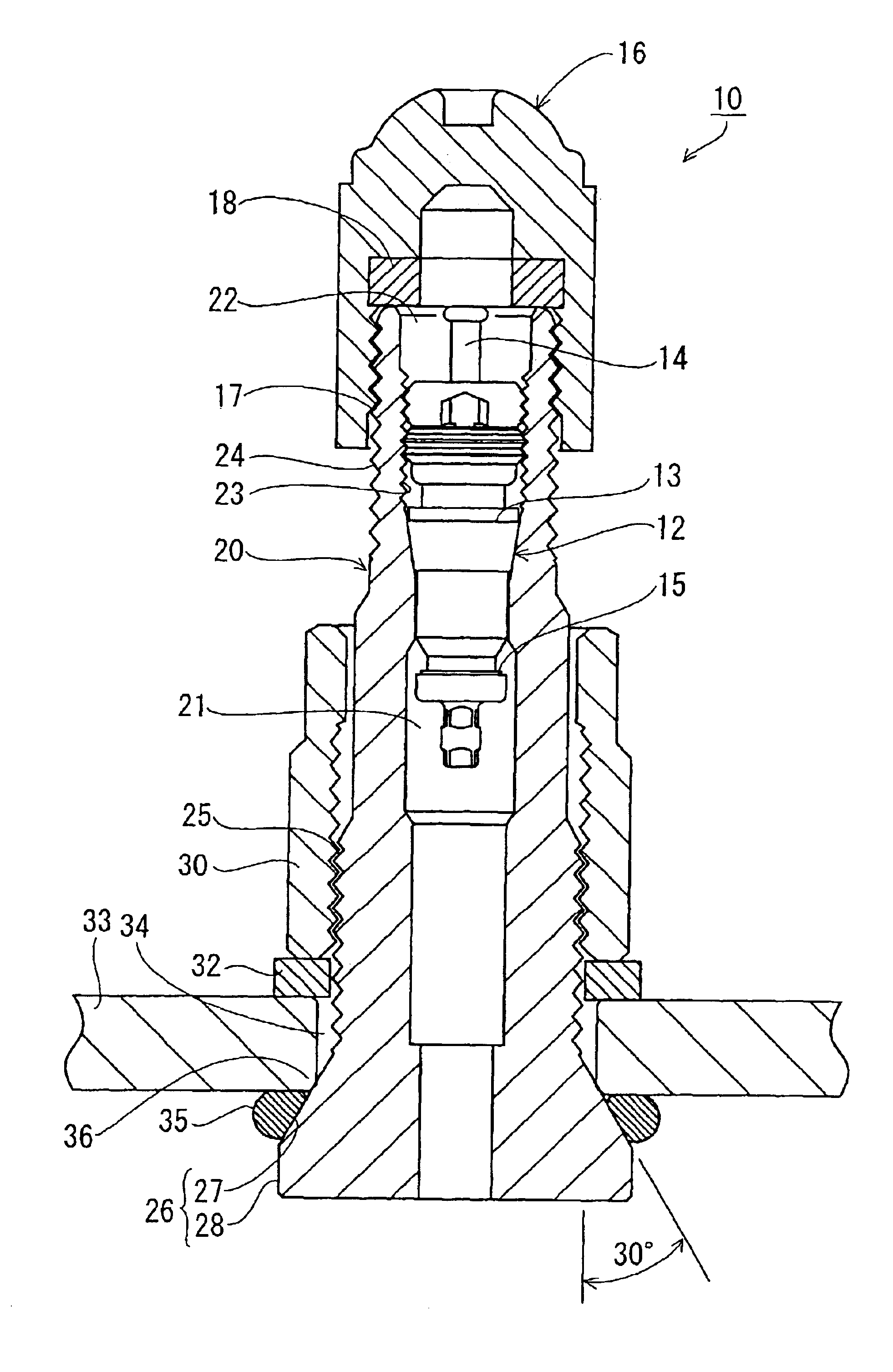
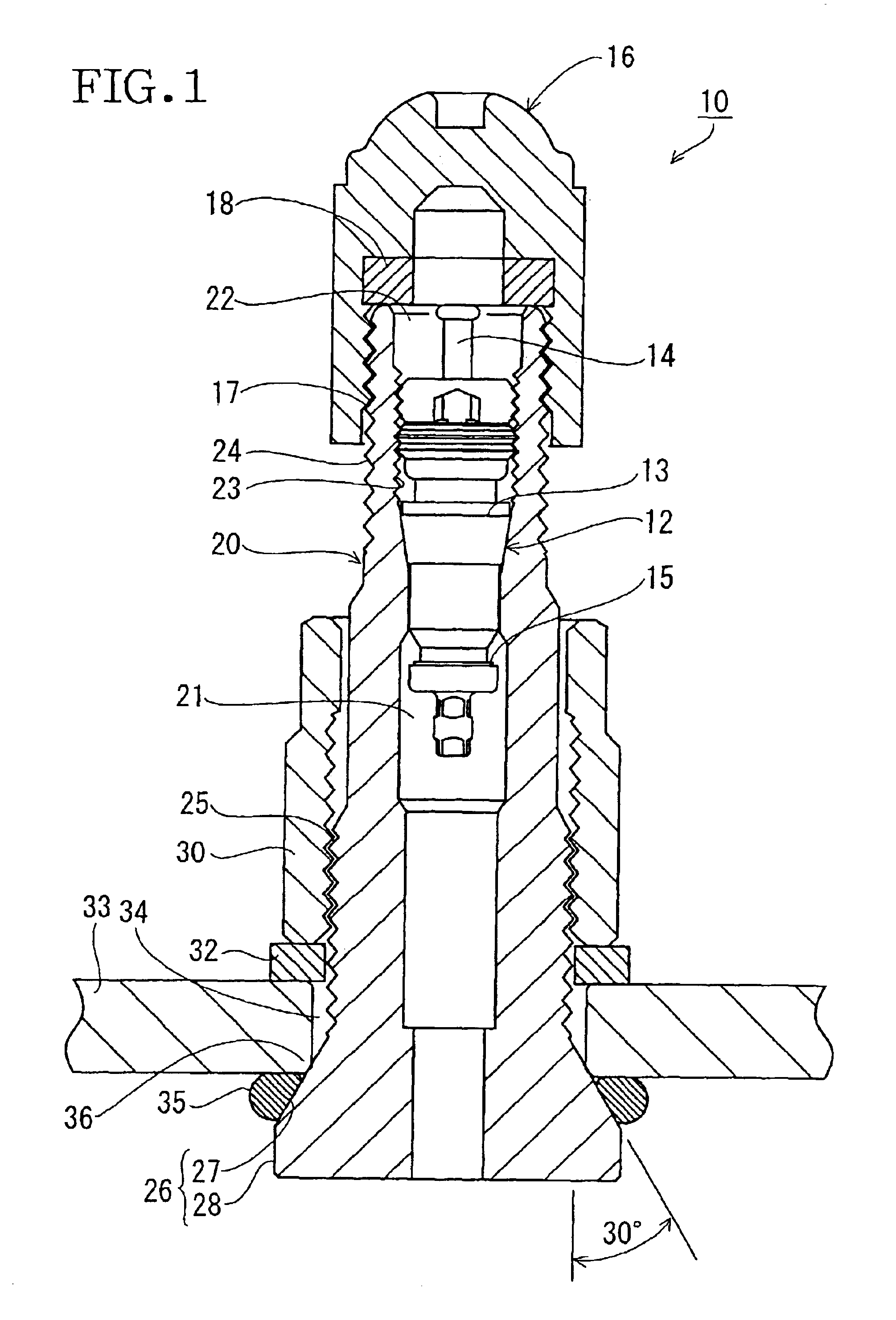
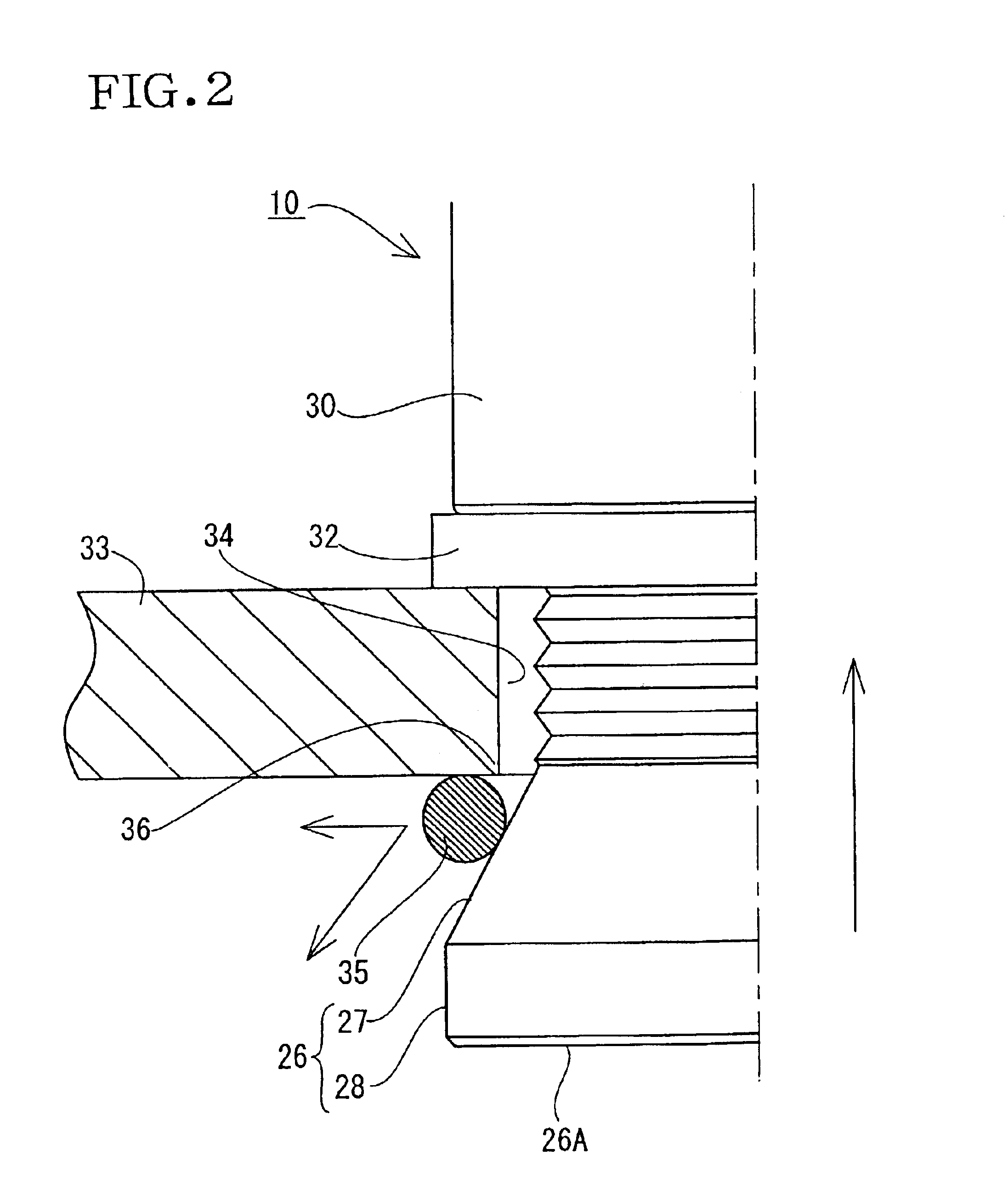
the invention will be described with reference to FIGS. 1 to 3. Referring to FIG. 1, the valve 10 in accordance with the invention is shown. The valve 10 is generally elongated and includes a generally cylindrical valve stem 20 and a valve core 12 provided in the valve stem. The valve stem 20 is made from brass, for example and has a central bore or an axial flow path 21 extending through the valve stem. The valve stem 20 is tapered from its proximal end toward its distal end and has an opening of the flow path 21 at the distal end thereof. The opening serves as a charging hole 22 through which a compressed gas is charged. The valve stem 20 has a female thread 23 formed in an inner periphery thereof located in the vicinity of the distal end.

The valve core 12 includes a cylindrical core body 13 and a moving shaft 14 extending through the core body 13. A coil spring (not shown) provided in the core body 13 urges the moving shaft 14 toward one side so that a valve element 15 provided o...


PUM


Abstract

A valve is generally elongated in shape and is inserted through an O-ring and amounting hole formed through a plate-shaped member. The valve includes a thread formed on an outer circumferential face of the valve so that a generally annular fitting is engaged therewith, an outer protruding wall protruding from the outer circumferential face of the valve to hold a circumferential edge of the mounting hole in cooperation with the fitting, a tapered portion formed in the outer protruding wall so as to be tapered toward the fitting and so as to abut against a part of the circumferential edge of the mounting hole, and a sealing portion disposed at a side farther away from the plate-shaped member than a portion of the protruding wall abutting against said circumferential edge part of the mounting hole so that each of the plate-shaped member and the sealing portion presses the O-ring against the other.

Description

BACKGROUND OF THE INVENTION1. Field of the InventionThis invention relates to a valve which is generally elongated and is mounted in a mounting hole formed through a plate-shaped member and a sealing structure for such a valve.2. Description of the Related ArtFIG. 5 illustrates a conventional valve 1 of the type described above. The valve 1 includes a generally annular flange 2 formed on a proximal end thereof. A grommet 3A is provided on a circumferential portion of the flange 2. The valve 1 is inserted through a mounting hole 4A formed in a steel plate 4, for example. Another grommet 3B and an annular fitting 5 are fitted with a part of the valve 1 having passed through the mounting hole 4A, in turn. The fitting 5 is brought into thread engagement with an outer thread of the valve 1 so that the valve is fixed in position with the steel plate 4 being held between the flange 2 and the fitting 5.In the above-described conventional valve 1, however, the grommets 3A and 3B are held bet...

Claims


Application Information

Patent Timeline
IPC IPC(8): B60C29/02B60C29/00F16J15/06
CPCB60C29/02Y10S251/90Y10T137/7668Y10T137/3786
Inventor KAYUKAWA, HISASHI
Owner PACIFIC INDUSTRIAL CO LTD
Why Eureka
Try Eureka