Fixation band for affixing a prosthetic heart valve to tissue

Inactive Publication Date: 2005-01-25
MEDTRONIC INC
View PDF5 Cites 383 Cited by
  • Summary
  • Abstract
  • Description
  • Claims
  • Application Information

AI Technical Summary

Benefits of technology

As a result, one object of the present invention is to provide novel apparatus for quickl

Problems solved by technology

While such surgery is typically successful, it is also highly traumatic to the body and the use of the heart-lung machine may raise issues of subtle mental impairment in the near term following surgery.
However, this can make it difficult to s

Method used


Image

  • Fixation band for affixing a prosthetic heart valve to tissue
  • Fixation band for affixing a prosthetic heart valve to tissue
  • Fixation band for affixing a prosthetic heart valve to tissue

Examples


Embodiment Construction

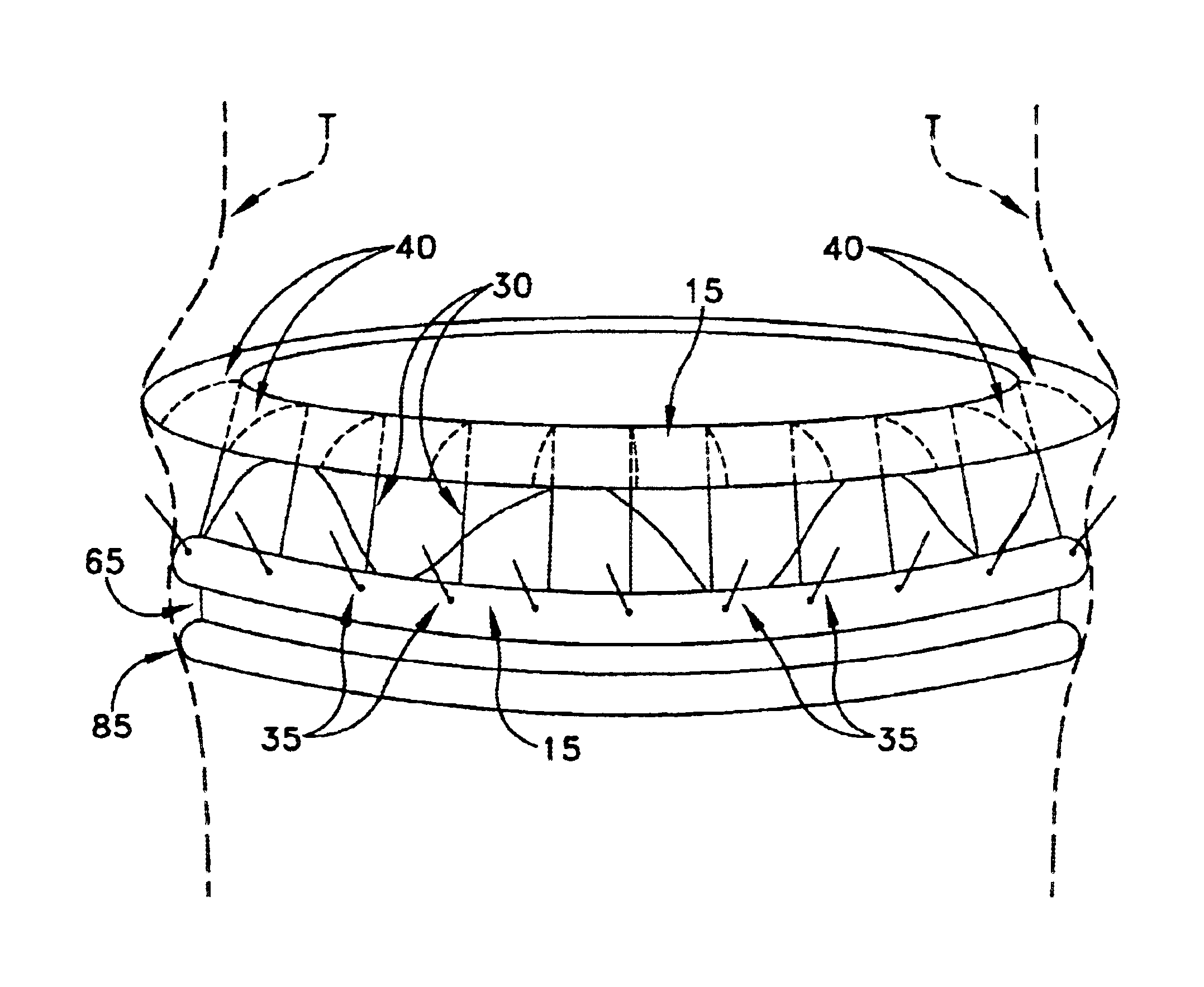
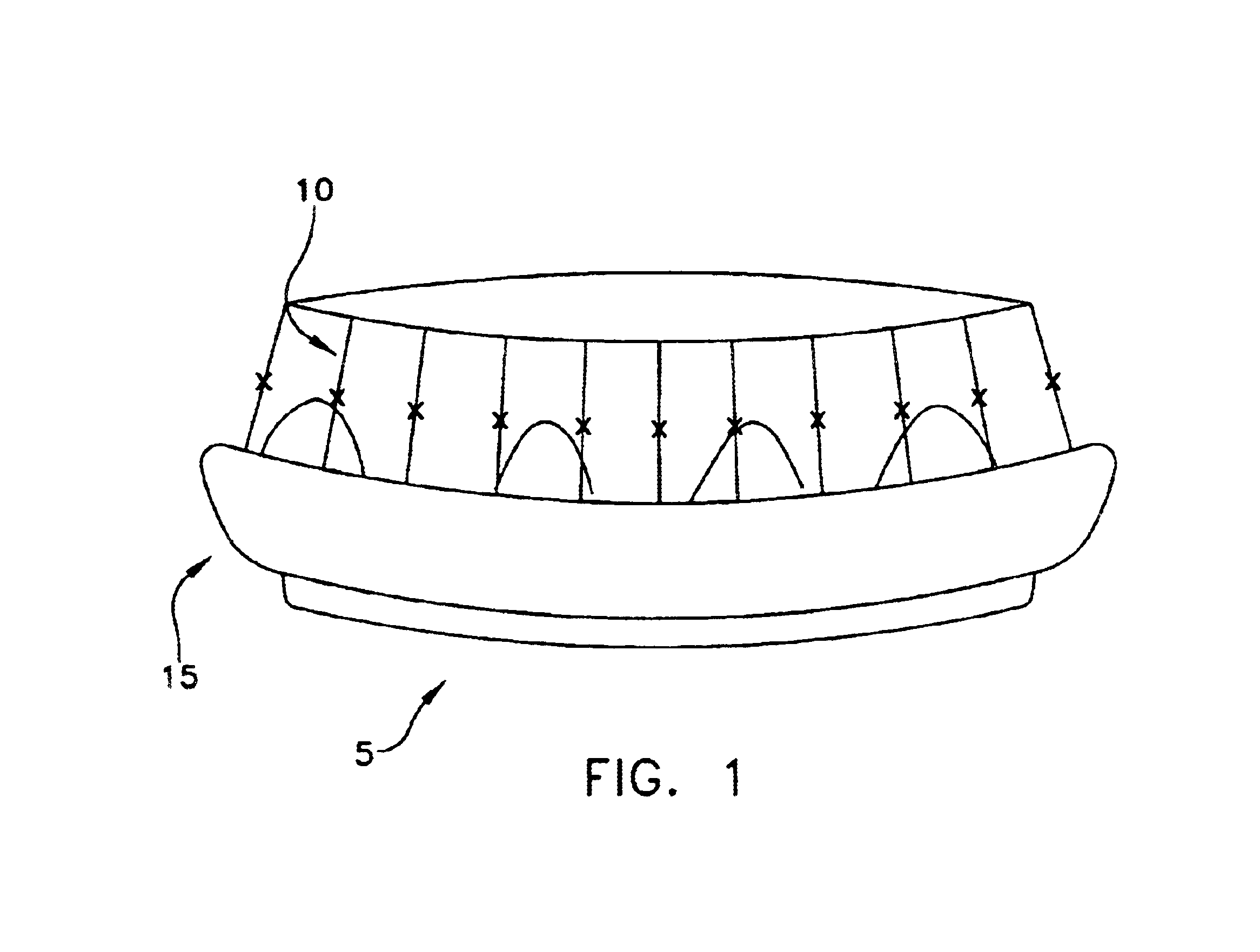
Looking first at FIG. 1, there is shown a fixation band 5 which comprises one preferred form of the invention. Fixation band 5 generally comprises a tubular frame 10 and a tube 15.

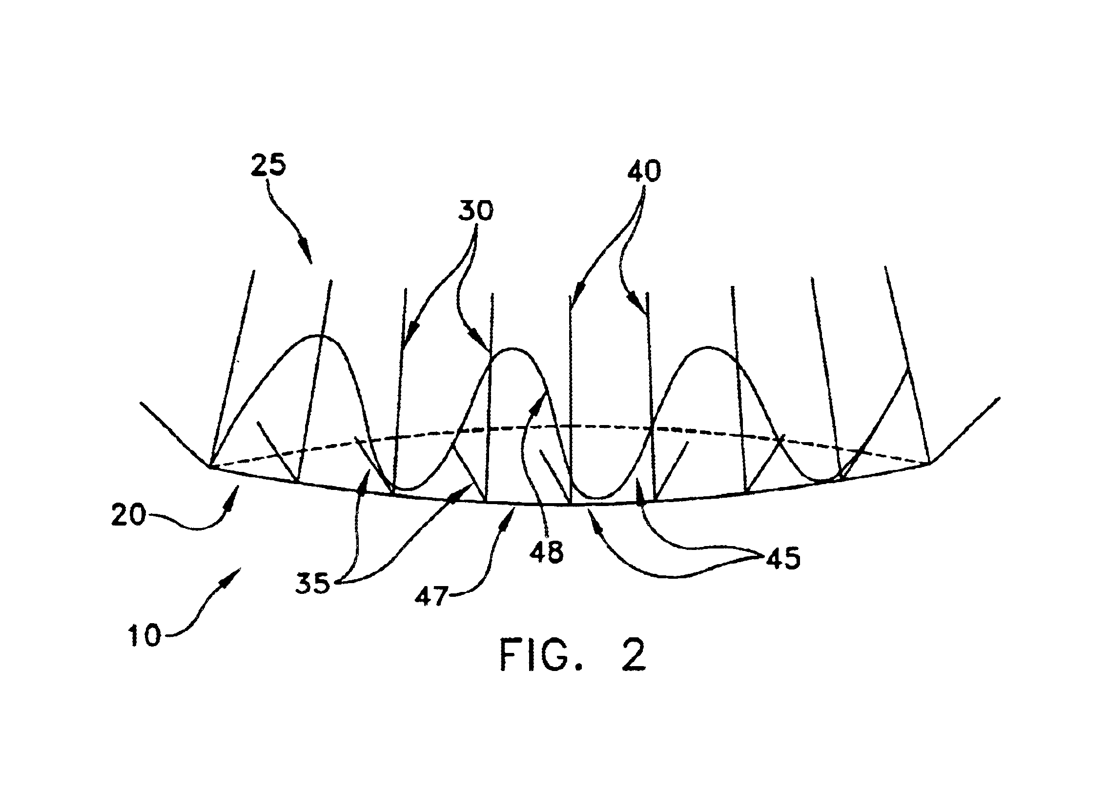
Tubular frame 10 is shown in greater detail in FIG. 2. Tubular frame 10 generally comprises a distal end 20 and a proximal end 25. Tubular frame 10 comprises a plurality of longitudinally-extending members 30 each having a hook 35 on its distal end, and fixation means 40 (discussed in further detail below) on its proximal end. Tubular frame 10 also comprises at least one laterally-extending member 45 for stabilizing the longitudinally-extending members 30 relative to one another so as to form the complete tubular frame. In one form of the invention, each laterally-extending member 45 extends completely around the circumference of the frame, in the manner shown in FIG. 2. Alternatively, a series of separate laterally-extending members 45 may be used to span the circumference of tubular frame 10. Furthermore...


PUM


Abstract

A prosthetic heart value assembly comprising a prosthetic heart valve and a fixation band. The fixation band comprises a tubular frame and a tube. The tubular frame comprises longitudinally-extending members having hooks on their distal ends and fixation means on proximal ends, and a stabilizing laterally-extending member. The tube is positioned inside the longitudinally-extending members, a distal end of the tube being everted over the hooks. A sewing cuff is formed in the tube. The prosthetic valve is secured to the fixation band by suturing a prosthetic valve sewing cuff to a fixation band sewing cuff. The prosthetic valve and fixation band are advanced to the valve's seat. The fixation band's hooks are passed through the wall of the everted tube and into surrounding tissue and the fixation band's fixation means are deployed.

Description

FIELD OF THE INVENTIONThis invention relates to surgical apparatus in general, and more particularly to prosthetic heart valves.BACKGROUND OF THE INVENTIONThe human heart consists of four chambers: the right atrium for receiving blood from systemic circulation; the right ventricle for receiving blood from the right atrium and pumping it to the lungs; the left atrium for receiving oxygenated blood from the lungs; and the left ventricle for receiving oxygenated blood from the left atrium and pumping it to systemic circulation.The human heart also consists of four valves: the tricuspid valve located between the right atrium and the right ventricle; the pulmonary valve located at the output of the right ventricle; the mitral valve located between the left atrium and the left ventricle; and the aortic valve located at the output of the left ventricle.In some circumstances (e.g., a birth defect, disease, etc.) a natural heart valve may need to be replaced by a prosthetic heart valve. In t...

Claims


Application Information

Patent Timeline
IPC IPC(8): A61F2/24
CPCA61F2/2409A61F2/2418A61F2220/0016A61F2250/0069
Inventor LIDDICOAT, JOHN R.
Owner MEDTRONIC INC
Why Eureka
Try Eureka