
Optical magnifier suitable for use with a microdisplay device

a micro-display device and optical magnifier technology, applied in the field of optical magnifiers, can solve the problems of magnifiers with the added labor expense of cementing two elements, inability to meet the desired +/10 degree field of view, and inability to meet the needs of cost-sensitive applications

Inactive Publication Date: 2005-01-25
MONUMENT PEAK VENTURES LLC
View PDF21 Cites 6 Cited by
  • Summary
  • Abstract
  • Description
  • Claims
  • Application Information

AI Technical Summary

Problems solved by technology

This is a new and challenging goal that did not previously exist for larger electronic displays used with correspondingly lower magnification lenses.
For micro-displays with full diagonals of less than 6 mm, this magnifier does not provide the desired + / −10 degree field of view.
Additionally, this magnifier has the added labor expense of cementing two elements to form a doublet, which may be unacceptable for cost-sensitive applications.
However, the LCD is quite large (33.65 mm full diagonal) and the resulting magnification is only about 11×, making it unsuitable for use with micro-displays of the scale contemplated here.

Method used


Image

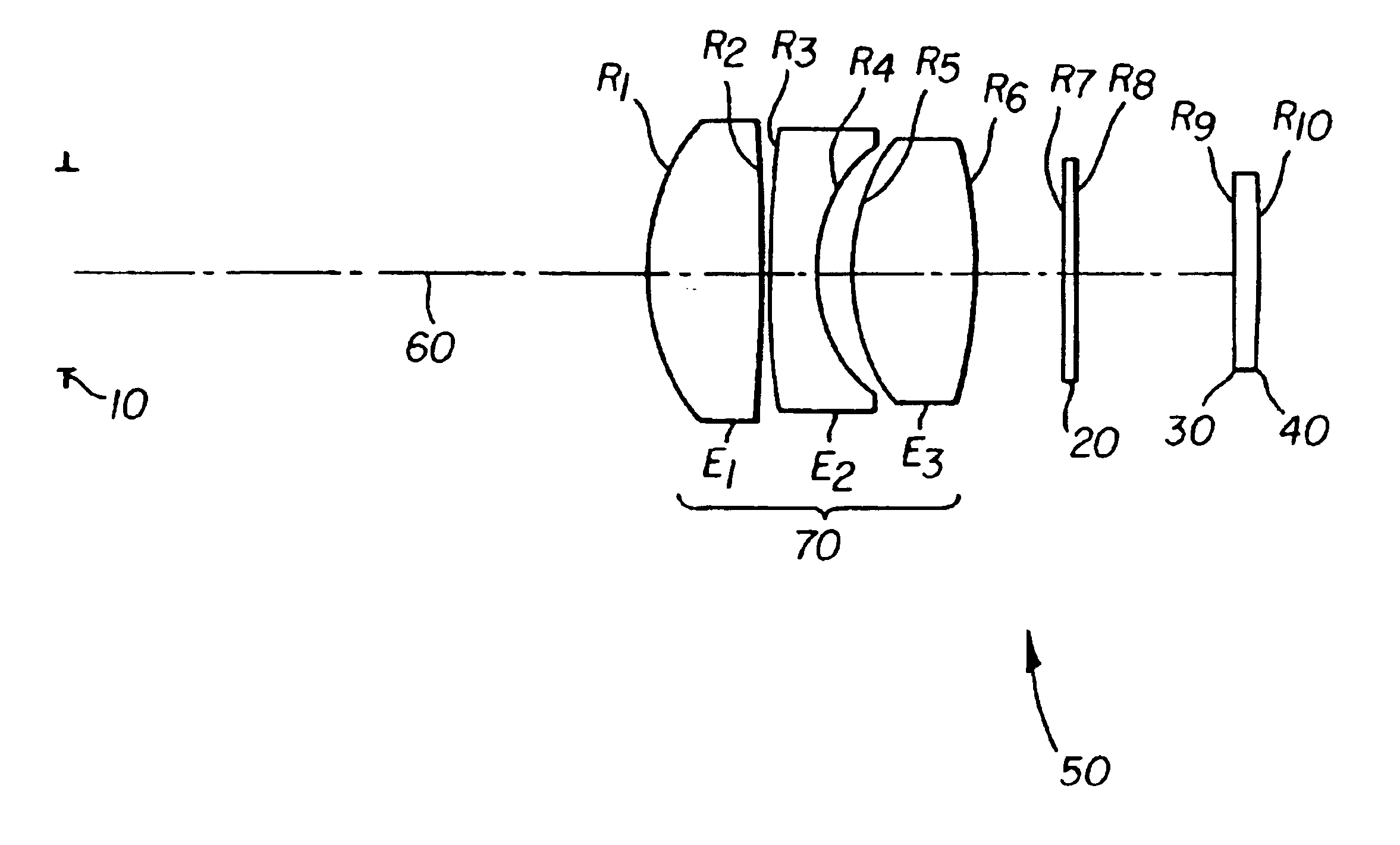
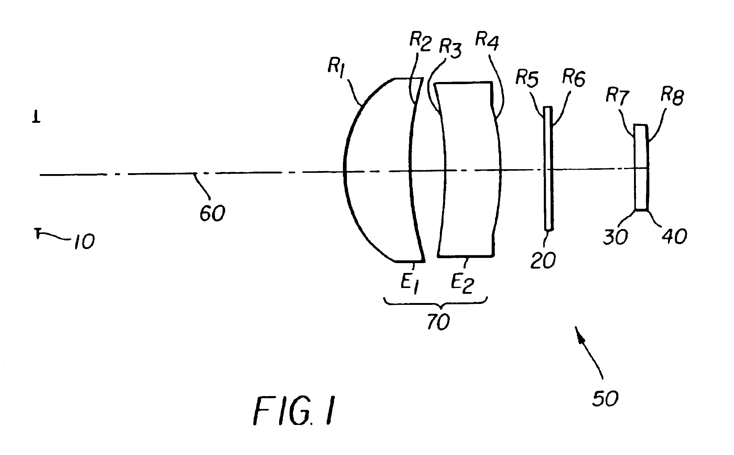
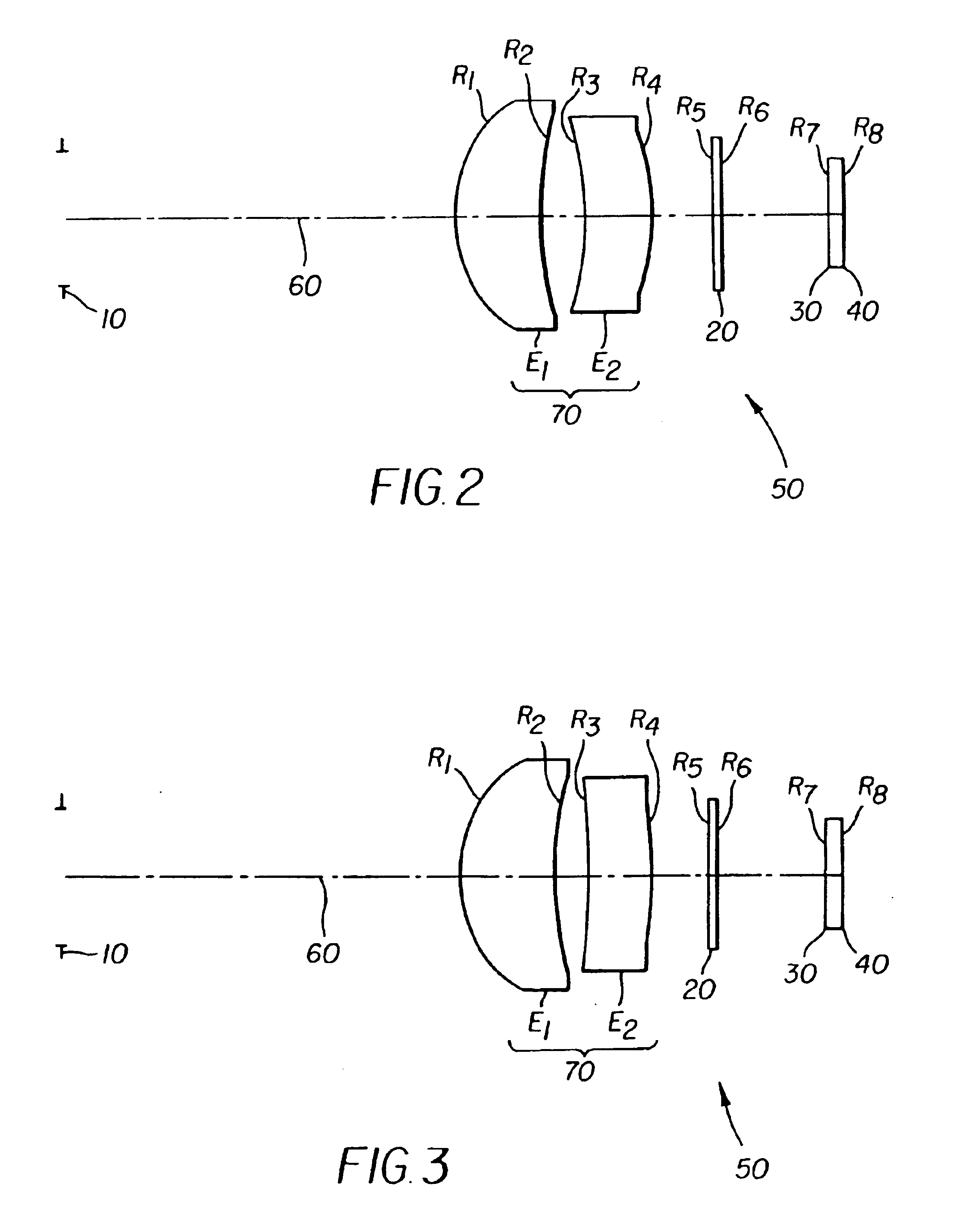
  • Optical magnifier suitable for use with a microdisplay device
  • Optical magnifier suitable for use with a microdisplay device
  • Optical magnifier suitable for use with a microdisplay device

Examples


Embodiment Construction

(with equal weights of 510, 560, 610 nm light) at a spatial frequency of 21 line pairs / mm;

[0028]FIG. 12 shows a plot of the through-focus Modulation Transfer Function (MTF) of the magnifier lens illustrated in FIG. 5, the MTF is polychromatic (with equal weights of 510, 560, 610 nm light) at a spatial frequency of 21 line pairs / mm;

[0029]FIG. 13 shows a plot of the through-focus Modulation Transfer Function (MTF) of the magnifier lens illustrated in FIG. 6, the MTF is polychromatic (with equal weights of 510, 560, 610 nm light) at a spatial frequency of 21 line pairs / mm; and

[0030]FIG. 14 shows a plot of the through-focus Modulation Transfer Function (MTF) of the magnifier lens illustrated in FIG. 7, the MTF is polychromatic (with equal weights of 510, 560, 610 nm light) at a spatial frequency of 21 line pairs / mm.

DETAILED DESCRIPTION OF THE INVENTION

[0031]The present description will be directed in particular to elements forming part of, or cooperating more directly with, apparatus in...


PUM


Abstract

An optical magnifier is provided. One general form of one example embodiment includes two lens elements, at least two aspheric surfaces, and at least one diffractive surface. Another general form of another example embodiment includes three lens elements, and at least three aspheric surfaces. At least two of the aspheric surfaces can be simple conics. The optical magnifier, suitable for use in an electronic display system, has an apparent field of view of at least + / −10 degrees; a magnification of at least 15×; a back focal length of at least 5 mm; and an eye relief greater than the effective focal length of the optical magnifier. The lens elements can be made from plastic.

Description

[0002]This application is a divisional of U.S. patent application Ser. No. 10 / 373,472 filed Feb. 24, 2003, in the name of Cahall, and assigned to the Eastman Kodak Company. now U.S. Pat. No. 6,785,054.FIELD OF THE INVENTION[0003]This invention relates generally to optical systems and in particular to optical magnifiers incorporated into and / or used in conjunction with other optical components.BACKGROUND OF THE INVENTION[0004]Optical Magnifiers (also referred to as “eyepieces” or “loupes”) are known. Typically, these optical devices are used to allow direct viewing of slides or other small objects or are used as part of other optical systems such as, for example, telescopes and viewfinders.[0005]Conventional optical magnifiers utilize magnifier lenses that provide an enlarged virtual image of a real object in front of a viewer's eye. It is generally preferable that such lenses, in combination with the object being viewed, provide an apparent field of view to the user in excess of + / −...

Claims


Application Information

Patent Timeline
IPC IPC(8): G02B13/00G02B25/00G02B13/18G02B5/18
CPCG02B13/003G02B25/008G02B25/001G02B13/0035
Inventor CAHALL, SCOTT C.
Owner MONUMENT PEAK VENTURES LLC
Learn More